Engine starter with torque variator

Active Publication Date: 2015-10-01
DENSO CORP
View PDF2 Cites 6 Cited by
  • Summary
  • Abstract
  • Description
  • Claims
  • Application Information

AI Technical Summary

Benefits of technology

The invention is an engine starter that solves the problem of difficulty starting an engine in cold conditions. It uses a torque variator to connect the planetary carrier and outer gear, ensuring stable starting of the engine. The torque variator can also increase the torque transmitted between the two gears to improve engine starting. The one-way clutch prevents the outer gear from rotating in a opposite direction to the sun gear, resulting in a speed reduction ratio greater than one and increasing the torque output.

Problems solved by technology

When the starter is required to achieve a high speed reduction ratio, but, the movable cam plate has failed to establish engagement with the housing through pressurized contact between the outer peripheral tapered surface of the movable cam plate and the inner peripheral tapered surface of the housing, there is a probability that the internal gear rotates in a direction opposite to rotation of the sun gear, thus resulting in a failure in transmitting torque outputted from the motor to the pinion gear to start the engine.
Additionally, when a depth of engagement of the pinion gear and the ring gear is small when the pinion is rotated in high speed, it may result in breakage of the pinon gear or the ring gear.

Method used


Image

  • Engine starter with torque variator
  • Engine starter with torque variator
  • Engine starter with torque variator

Examples


first embodiment

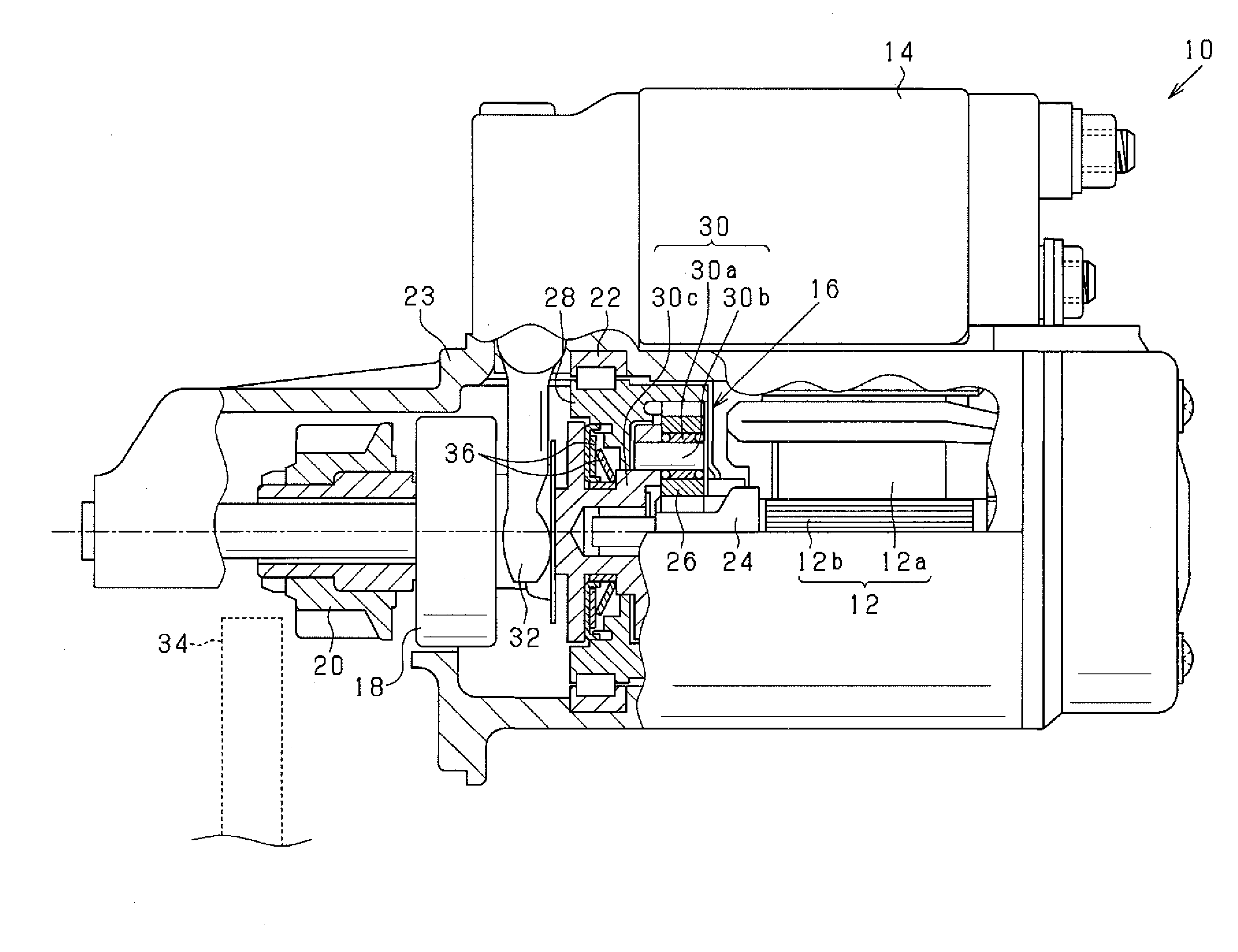
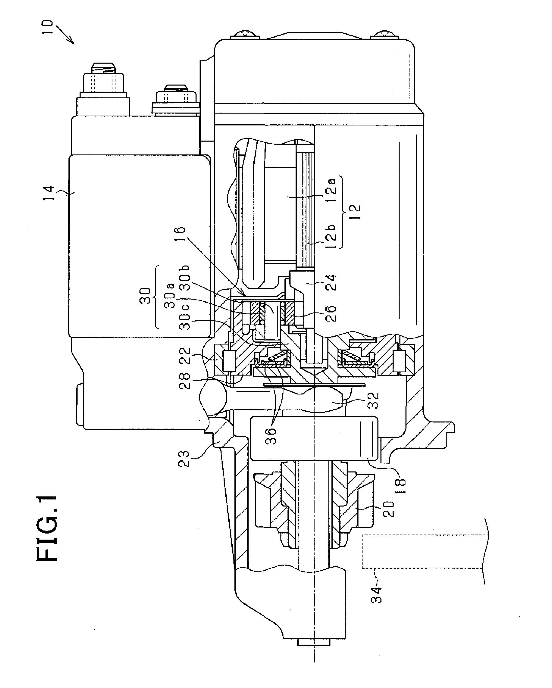
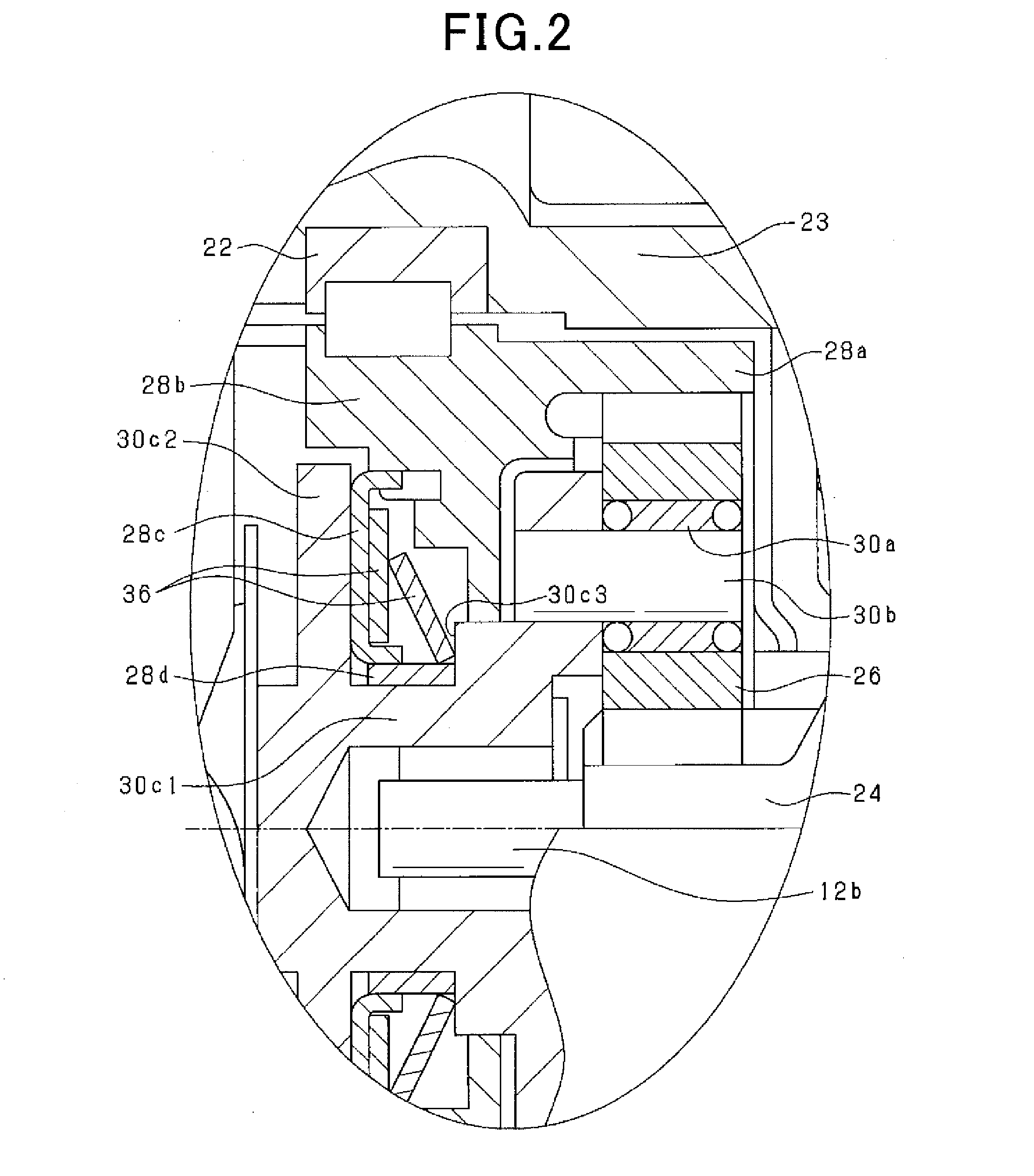
[0043]Referring to the drawings, wherein like reference numbers refer to like parts in several views, particularly to FIGS. 1 and 2, there is shown a starter 10 for an engine such as an automotive internal combustion engine according to the first embodiment.

[0044]The starter 10 includes an electric motor 12, a magnet switch 14, a planetary gear train 16, an overrunning clutch 18, a pinion gear 20, an one-way clutch 22, and a housing 22. The electric motor 12 works to produce torque. The magnet switch 14 controls an on-off operation of the electric motor 12. The overrunning clutch 18 is connected to an output of the planetary gear train 16. The pinion gear 20 works to output torque, as transmitted from the planetary gear train 16 through the overrunning clutch 18. The housing 23 stores the above components therein.

[0045]The magnet switch 14 is equipped with an exciting coil (not shown) and a plunger (not shown) disposed to be slidable within the exciting coil. The exciting coil is su...

second embodiment

[0072]FIG. 5 is a partial sectional view which illustrates the starter 10 according to the second embodiment which is different from the first embodiment in use of an electromagnetic clutch as a variable speed reducer also called a torque variator which includes the outer gear 28, the planetary carrier 30, and the spring mechanism 36 and works to vary the torque transmitted from the outer gear 28 to the planetary carrier 30 in the first embodiment. The same reference numbers as employed in the first embodiment of FIG. 1 will refer to the same parts, and explanation thereof in detail will be omitted here.

[0073]The electromagnetic clutch includes an exciting coil 38a which is energized by the current supplied from the battery, a housing 38b which forms a magnetic circuit around the exciting coil 38a, and a clutch plate 28e which faces an end surface of the housing 38b. The clutch plate 28e is made of an annular disc and movable in the axial direction of the starter 10 (i.e., the cente...

third embodiment

[0084]The starter 10 of this embodiment is different from that in the second embodiment only in the speed reduction ratio switching operation. Other arrangements are identical, and explanation thereof in detail will be omitted here.

[0085]FIG. 9 is a flowchart of a sequence of logical steps or program to execute the speed reduction ratio switching operation. The program is performed cyclically by the controller 10a at a given time interval. The same step numbers as employed in FIG. 7 refer to the same operations.

[0086]After the time elapsed since a YES answer was obtained in step S10 is counted up in step S12, the routine then proceeds to step S20 wherein the exciting coil 38a is deenergized to establish a speed reduction ratio of five in the planetary gear train 16. The routine then proceeds to step S22 wherein it is determined whether the elapsed time, as derived in step S10, has reached a reference time Ta or not. If a NO answer is obtained, then the routine repeats step S22. Alte...


PUM


Abstract

A starter for an engine is equipped with a planetary gear train as a torque variator to change torque used to start the engine. The torque variator is capable of changing the degree of torque which is transmitted between a planetary carrier and an outer gear of the planetary gear train, thereby changing a ratio of speed of a sun gear to speed of the planetary carrier of the planetary gear train to increase or decrease the degree of torque required to start the engine. This ensures the stability in starting the engine, for example, in cold conditions and achieves a quick start of the engine as needed.

Description

CROSS REFERENCE TO RELATED DOCUMENT[0001]The present application claims the benefit of priority of Japanese Patent Application No. 2014-63814 filed on Mar. 26, 2014 and No. 2014-111310 filed on May 29, 2014, disclosures of which are incorporated herein by reference.BACKGROUND OF THE INVENTION[0002]1 Technical Field[0003]This disclosure relates generally to an engine starter designed to apply torque to a ring gear of an engine.[0004]2 Background Art[0005]There is a need to rotate a pinion gear of a starter at high speed to shorten the time required to start an internal combustion engine. When the pinion gear is rotated at high speed, it requires an electric motor of the starter to be increased in size in order to produce a degree of torque great enough to start the engine in cold conditions.[0006]In order to meet the above requirement, Japanese Patent First Publication No. 2004-218627 proposes a starter which is designed to change a speed reduction ratio of an output shaft of an elec...

Claims


Application Information

Patent Timeline
IPC IPC(8): F02N15/04F16H3/74
CPCF16H3/74F02N15/046F02N11/00F02N15/025F02N15/067F02N2300/104Y10T74/137F16H3/725F16H2200/2005F16H2200/203F16H2200/2066F16H2200/2082
Inventor FUJITA, TATSUYA
Owner DENSO CORP
Why Eureka
Try Eureka