Control device for an internal combustion engine

Inactive Publication Date: 2008-11-20
MITSUBISHI ELECTRIC CORP
View PDF9 Cites 16 Cited by
  • Summary
  • Abstract
  • Description
  • Claims
  • Application Information

AI Technical Summary

Benefits of technology

[0014]The present invention has been made in view of the above-mentioned circumstances, and therefore an object of the present invention is to provide a control device for an internal combustion engine which sets an initial value of an integral term at a time of starting a phase angle feedback control by a simple control logic, thereby making it possible to achieve both of suppression of an overshoot quantity of a real phase angle and an improvement in a response time.
[0016]According to the present invention, the initial value of the integral term at the time of starting the phase angle feedback control operation is set based on the temperature parameter of the internal combustion engine, and the control correction quantity that has been calculated by the feedback control operation is corrected by the battery voltage so that an operation quantity is output to the hydraulically controlled solenoid valve. As a result, the actual position of the hydraulically controlled solenoid valve in the retention state is not deviated from the original neutral position toward the advance side. Therefore, even in a case where the target phase angle is set to the advance side where the valve overlap between the intake valve and the exhaust valve is originally large, the valve overlap does not become excessive, and deterioration of the startability of the internal combustion engine which is caused by the excessive internal EGR volume (exhaust gas recirculation volume) can be prevented. In addition, because it is unnecessary to limit the target phase angle toward the advance side, it is possible to improve the startability at a low temperature.

Problems solved by technology

However, because the fixed value of the retention duty set as described above varies in the tolerance and also changes with time, the fixed value may not naturally coincide with the learned value that compensates those variations.
As a result, the subsequent controllability of the cam phase control is also deteriorated.
In particular, in the case where the inconsistency occurs at the advance side, and a target phase angle is set to the advance side where a valve overlap of the intake valve and the exhaust value is originally large, it is also known that the valve overlap becomes excessive, and an internal exhaust gas recirculation volume (EGR volume) is resultantly excessive, which may deteriorate the combustion quality.
In particular, in the case where the deviation is caused at the advance side, and the target phase angle is set to the advance side where the valve overlap between the intake valve and the exhaust valve is originally large, the valve overlap becomes excessive, and the resultant internal EGR quantity becomes excessive, thereby deteriorating the startability of the internal combustion engine.
Further, in the case where the learning of the retention duty value has not yet been completed, the control of the advance side is limited because the target phase angle is limited.
When the intake fuel-air mixture is returned into the intake pipe at the time of cranking where the rotation speed of the internal combustion engine is extremely low, a real compression ratio is lowered to thereby make the startability difficult.
In particular, at a low temperature where the volume of the fuel-air mixture is small, there arises such a problem that the fuel-air mixture is not sufficiently compressed even if cranking is conducted, and the startability is further deteriorated.

Method used


Image

  • Control device for an internal combustion engine
  • Control device for an internal combustion engine
  • Control device for an internal combustion engine

Examples


first embodiment

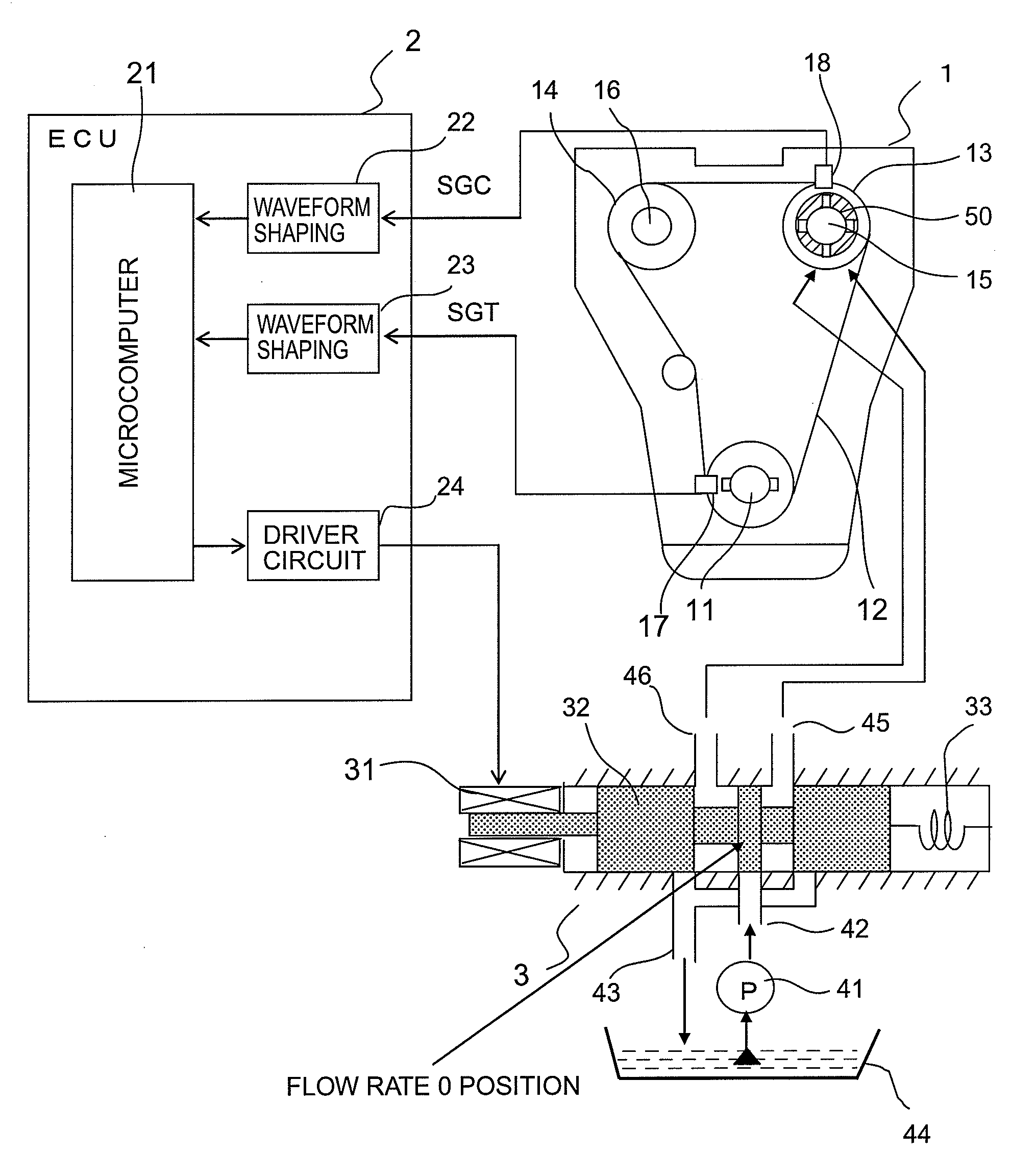
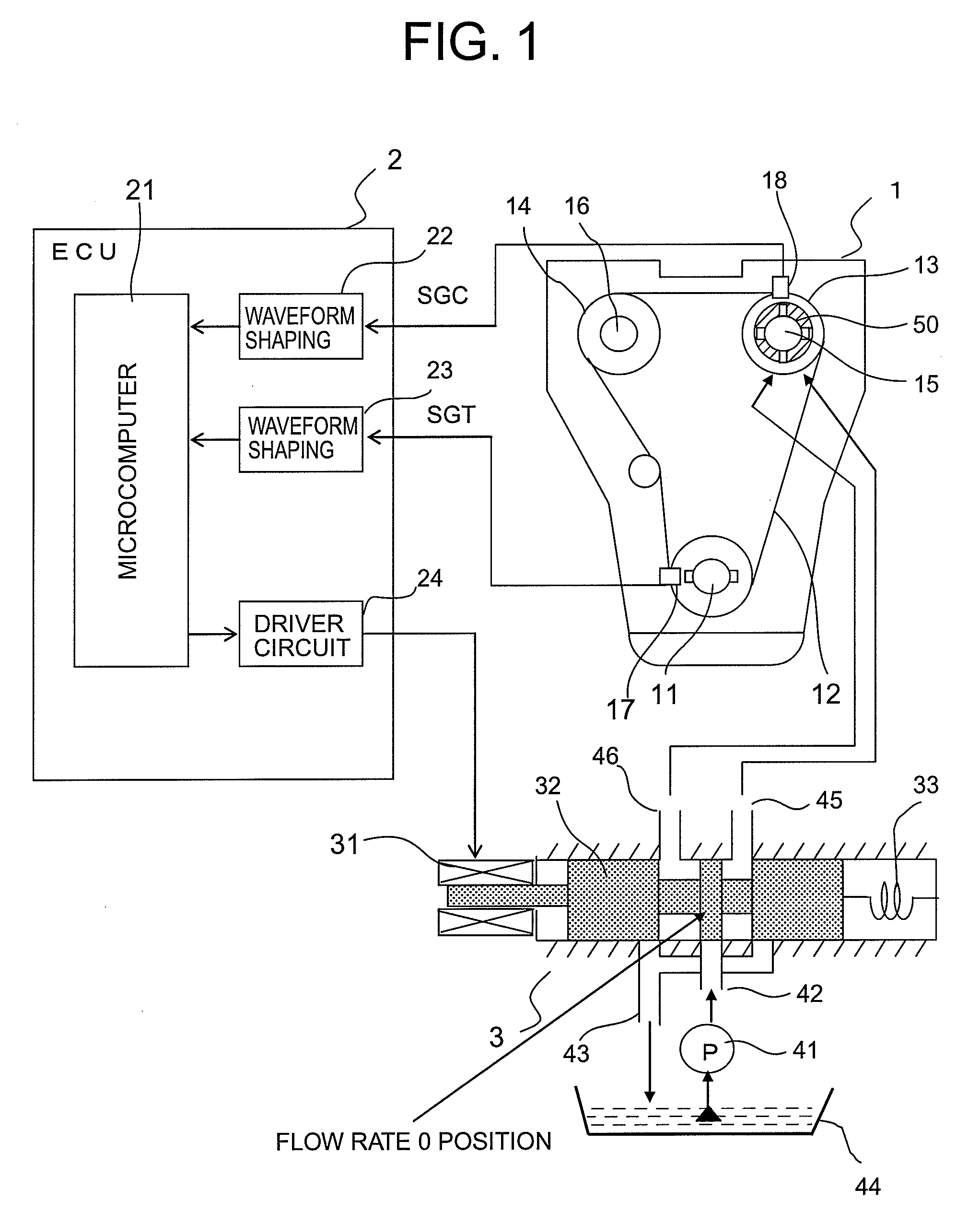
[0037]Hereinafter, a description will be given of an embodiment of the present invention with reference to the accompanying drawings. FIG. 1 is a diagram showing an outline structure of a valve timing control device for an internal combustion engine according to a first embodiment of the present invention. In a valve timing control device for an internal combustion engine shown in FIG. 1, a driving force is transmitted from a crank shaft 11 of an internal combustion engine 1 to a pair of timing pulleys 13 and 14 through a timing belt 12. The pair of timing pulleys 13 and 14 that are rotationally driven in synchronism with the crank shaft 11 are equipped with a pair of cam shafts 15 and 16 as driven shafts, respectively, and an intake valve and an exhaust valve which are not shown are driven to be opened or closed by those cam shafts 15 and 16.

[0038]With the above configuration, the intake valve and the exhaust valve are driven to be opened or closed in synchronism with rotation of t...


PUM


Abstract

Provided is a control device for an internal combustion engine, including a crank angle sensor, a cam angle sensor, a real phase angle detector for detecting a real phase angle of a cam shaft based on a detection signal of the sensors, a target phase angle setting unit including a temperature parameter and battery voltage, for setting a target phase angle of the cam shaft based on an operating state of the internal combustion engine, and a phase angle feedback control unit for conducting feedback control operation so that the real phase angle coincides with the target phase angle, and for calculating an operation quantity to a hydraulically controlled solenoid valve, in which the feedback control unit sets an integral term initial value when starting the feedback control operation according to the temperature parameter, corrects a control correction quantity by the battery voltage, and outputs the operation quantity to the solenoid valve.

Description

BACKGROUND OF THE INVENTION[0001]1. Field of the Invention[0002]The present invention relates to a control device for an internal combustion engine for controlling the operation timing of an intake valve or an exhaust valve in the internal combustion engine.[0003]2. Description of the Related Art[0004]Up to now, there has been known a valve timing control device for an internal combustion engine, which changes a phase angle of a cam shaft with respect to a crank shaft in the internal combustion engine to thereby change a valve switching timing of the intake valve or the exhaust valve (for example, refer to JP 2001-234765 A).[0005]The valve timing control device of this type is provided with a crank angle sensor for outputting a crank angle signal at a reference rotation position of the crank shaft, and a cam angle sensor for outputting a cam angle signal at a reference rotation position of the cam shaft. A real phase angle of the cam shaft is detected based on detection signals of t...

Claims


Application Information

Patent Timeline
IPC IPC(8): F02D13/02F01L1/344
CPCF01L1/34F01L1/3442F01L2001/34426F01L2800/00F02D13/0215F02D35/025F02D41/009F02D41/064F02D41/1482F02D2041/001
Inventor WATANABE, SHINJITANAKA, TORUTAKAHASHI, TATSUHIKO
Owner MITSUBISHI ELECTRIC CORP
Why Eureka
Try Eureka