Control device for engine and control method of engine

a control device and control method technology, applied in the direction of engine starters, electric control, instruments, etc., can solve the problems of deteriorating engine startability, reducing the rotation speed of the top dead center, and deteriorating precision of detecting the crank position, so as to suppress the erroneous detection of the toothless part of the timing rotor

Inactive Publication Date: 2018-11-29
TOYOTA JIDOSHA KK
View PDF11 Cites 2 Cited by
  • Summary
  • Abstract
  • Description
  • Claims
  • Application Information

AI Technical Summary

Benefits of technology

[0004]In a case where the crank position of the crankshaft is detected by the timing rotor having a toothless part and the crank angle sensor, the toothless part of the timing rotor may be erroneously detected due to the rotational deviation and the decrease in rotation speed of when the crank rotation speed is slow and the top dead center (TDC) is exceeded, and thus the precision of detecting the crank position may deteriorate. In particular, in a case where an engine start is performed by only combustion without using a starter, since the crank rotation speed is extremely slow and a change rate of rotation fluctuation is large, in some cases, the decrease in rotation speed of when the top dead center is exceeded may erroneously be detected as the toothless part of the timing rotor. In a case where the exceeding of the top dead center is erroneously detected as the toothless part of the timing rotor, the crank position is erroneously detected, and thus the startability of the engine may deteriorate.
[0005]The disclosure provides a control device and a control method for an engine including a timing rotor provided with a toothless part and a crank angle sensor configured to output a pulse signal according to passing of a tooth of the timing rotor, the control device being capable of suppressing erroneous detection of the toothless part of the timing rotor.

Problems solved by technology

In a case where the crank position of the crankshaft is detected by the timing rotor having a toothless part and the crank angle sensor, the toothless part of the timing rotor may be erroneously detected due to the rotational deviation and the decrease in rotation speed of when the crank rotation speed is slow and the top dead center (TDC) is exceeded, and thus the precision of detecting the crank position may deteriorate.
In particular, in a case where an engine start is performed by only combustion without using a starter, since the crank rotation speed is extremely slow and a change rate of rotation fluctuation is large, in some cases, the decrease in rotation speed of when the top dead center is exceeded may erroneously be detected as the toothless part of the timing rotor.
In a case where the exceeding of the top dead center is erroneously detected as the toothless part of the timing rotor, the crank position is erroneously detected, and thus the startability of the engine may deteriorate.
However, when the piston passes the top dead center, since the crank rotation speed is slow, the pulse input interval time becomes longer than a pulse input interval time at a crank rotation speed at which the detection of the toothless part is possible.

Method used


Image

  • Control device for engine and control method of engine
  • Control device for engine and control method of engine
  • Control device for engine and control method of engine

Examples


Embodiment Construction

[0028]Hereinafter, embodiments of the disclosure will be described with reference to the drawings.

[0029]Engine

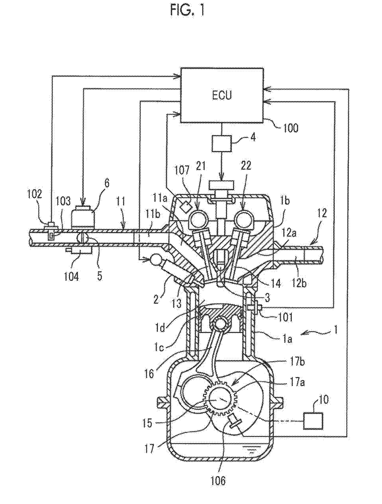
[0030]FIG. 1 is a diagram illustrating a schematic configuration of an engine (internal combustion engine) to which the disclosure is applied. In FIG. 1, only the configuration of one cylinder of the engine is illustrated.

[0031]An engine 1 of the embodiment is a cylinder injection engine having four cylinders (first cylinder #1 to fourth cylinder #4) mounted in a vehicle, and a piston 1c which reciprocates in an up-down direction is provided in a cylinder block 1a that constitutes each cylinder. The piston 1c is connected to a crankshaft 15 via a connecting rod 16, and the reciprocation of the piston 1c is converted into the rotation of the crankshaft 15 via the connecting rod 16.

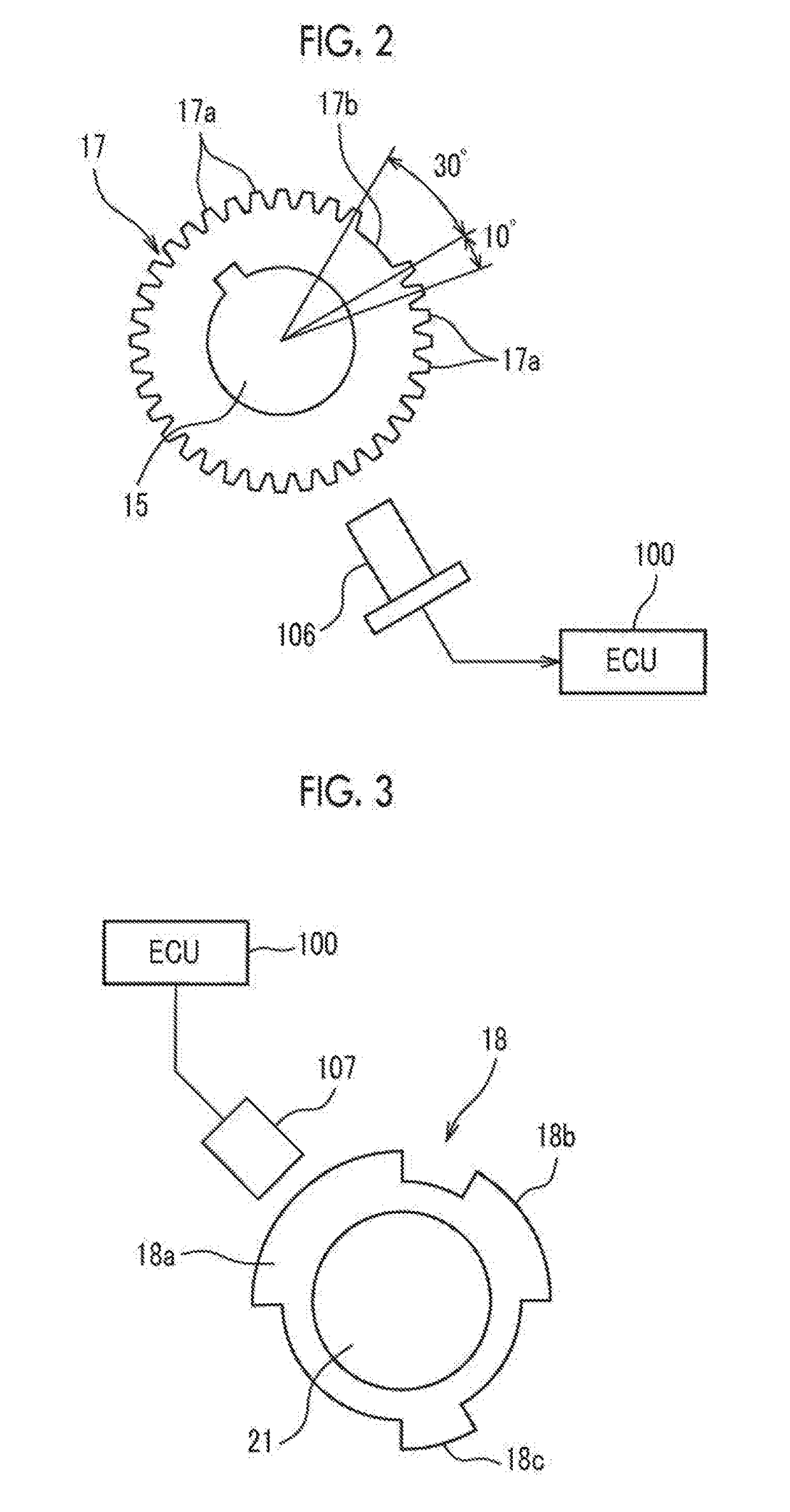
[0032]A timing rotor 17 is attached to the crankshaft 15. A plurality of teeth (projections) 17a is provided on the outer periphery of the timing rotor 17 such that the teeth 17a are disposed at an ...


PUM


Abstract

The application discloses a control device and a control method for an engine. The control device includes an electronic control unit configured to execute a stop-and-start control of automatically stopping the engine when a predetermined automatic stop condition is established and automatically restarting the engine when a predetermined automatic-restart condition is established during the automatic stop of the engine, and in a case where the automatic-restart condition is established during fuel cut-off according to the automatic stop of the engine, prohibit detection of the toothless part based on the pulse signal output from the crank angle sensor, for a period until the crankshaft is rotated by a predetermined crank angle or more after the automatic-restart condition is established.

Description

INCORPORATION BY REFERENCE[0001]The disclosure of Japanese Patent Application No. 2017-102854 filed on May 24, 2017 including the specification, drawings and abstract is incorporated herein by reference in its entirety.BACKGROUND1. Technical Field[0002]The present disclosure relates to a control device and a control method for an engine mounted in a vehicle.2. Description of Related Art[0003]In an engine (internal combustion engine), a crank position of a crankshaft is detected by a timing rotor provided on the crankshaft and a crank angle sensor, and fuel injection and ignition for a cylinder are controlled. In an engine in which a stop-and-start control can be executed, it is known that a restart control of the engine is performed by performing cylinder discrimination based on a toothless part provided on the timing rotor of the crankshaft and the output from a cam angle sensor at the engine stop time (for example, Japanese Unexamined Patent Application Publication No. 2012-062802...

Claims


Application Information

Patent Timeline
Patent Type & Authority Applications(United States)
IPC IPC(8): F02N11/08
CPCF02N11/0844F02N11/0818F02N2200/021F02N2200/022F02N2300/2011F02D41/009F02D41/042F02D41/065F02D41/062F02D2041/0092F02P7/0675G01M15/046G01M15/048G01P3/489Y02T10/40B60W30/192
Inventor ENOMOTO, HIROSHI
Owner TOYOTA JIDOSHA KK
Why Eureka
Try Eureka