

Starter for internal combustion engine
- Summary
- Abstract
- Description
- Claims
- Application Information
AI Technical Summary
Benefits of technology
Problems solved by technology
Method used
Image

Examples
first embodiment
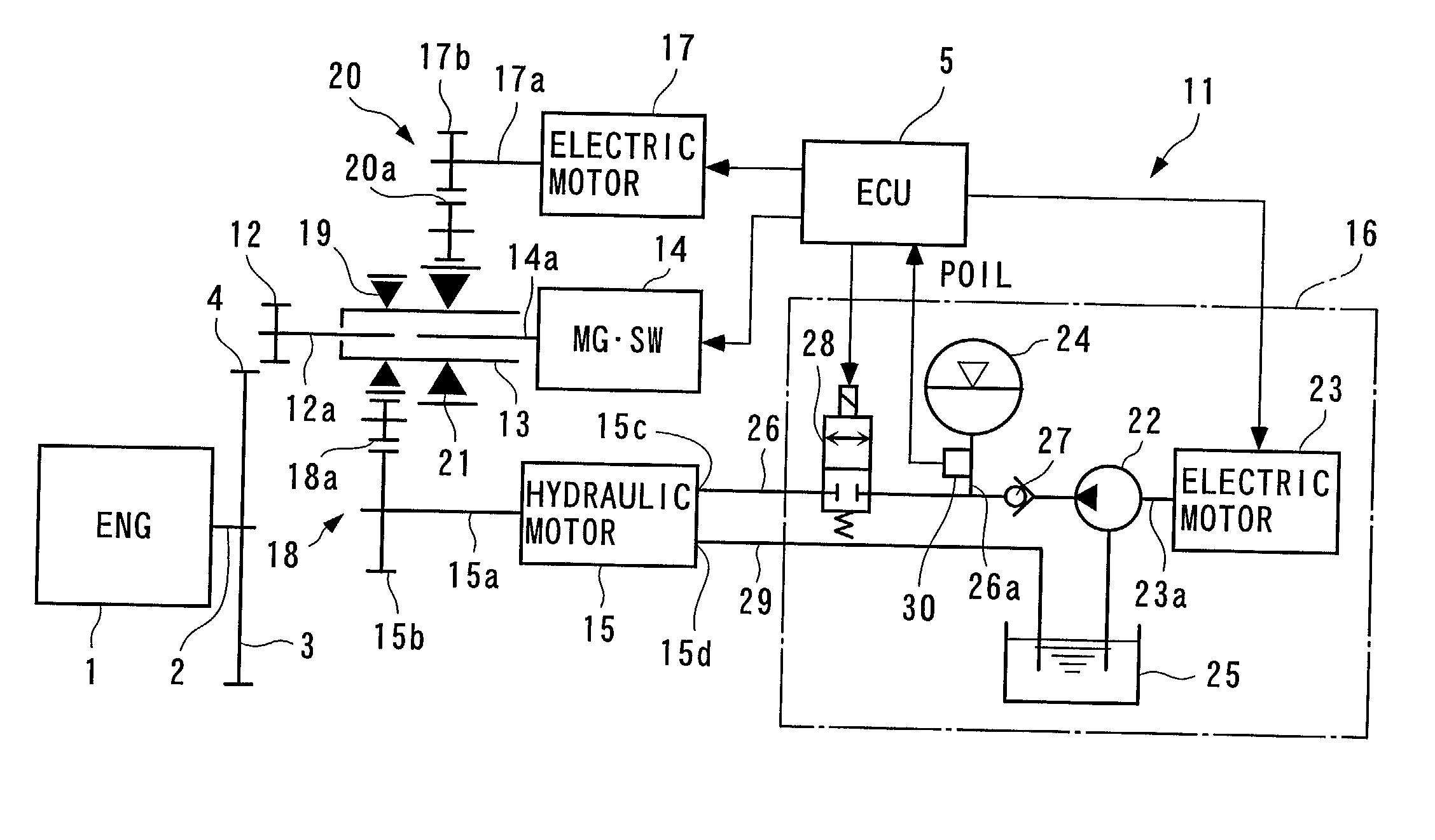
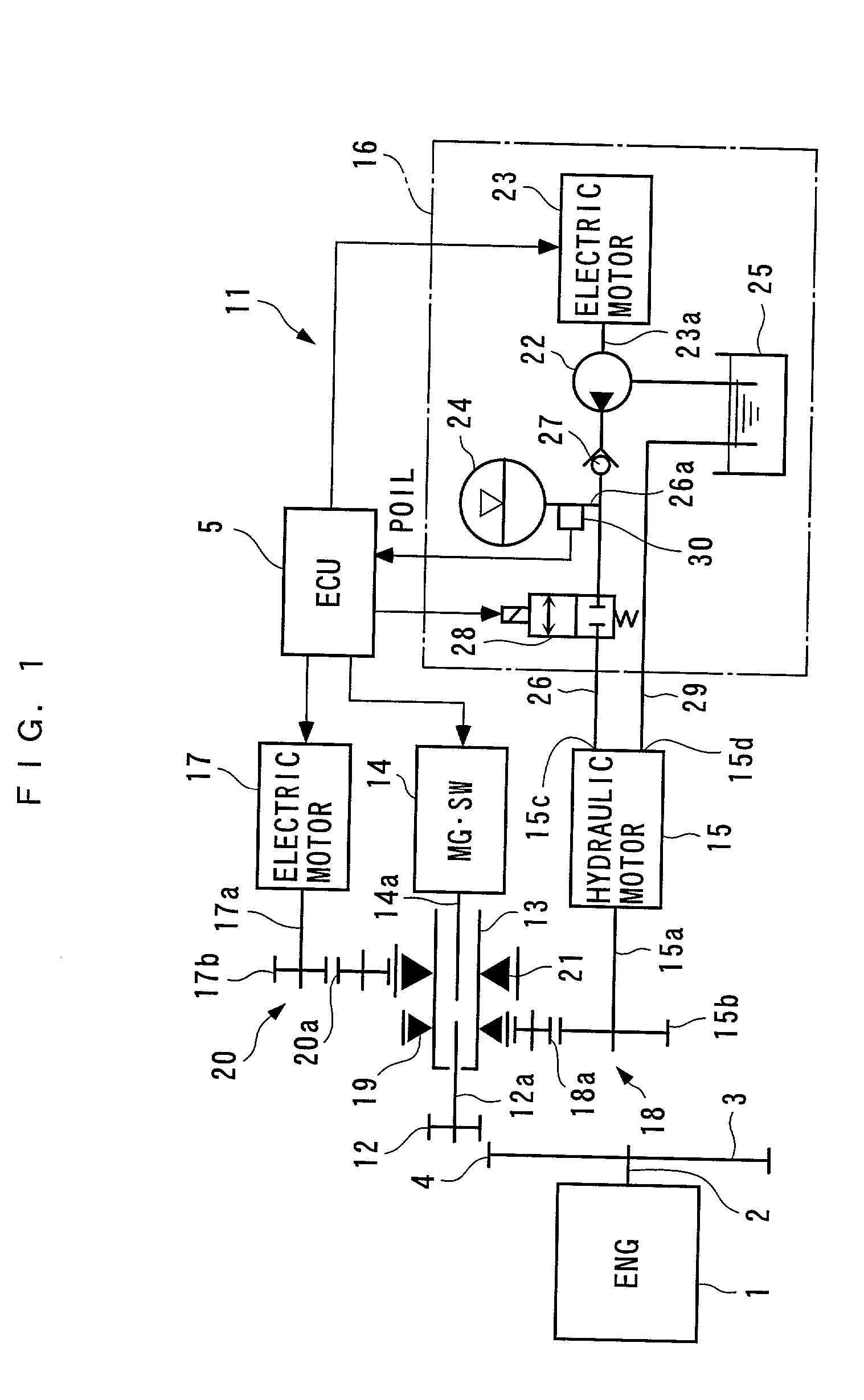
[0022] FIG. 1 illustrates a starter for an internal combustion engine according to the present invention. An internal combustion engine (hereinafter simply called the "engine") (ENG), designated by reference numeral 1, has a crank shaft 2 to which a fly wheel 3 is fixed. A ring gear 4 comprised of a helical gear is integrally formed on the outer peripheral surface of the fly wheel 3.
[0023] A starter 11, on the other hand, comprises the ring gear 4 (driven gear); a pinion gear 12 (driving gear); an output shaft 13 having one end coupled to the pinion gear 12; a magnet switch (MG.SW) 14 for moving the pinion gear 12 into mesh with the ring gear 4 upon starting the engine 1; a hydraulic motor 15 (hydraulic actuator) for driving the pinion gear 12 to rotate upon starting; a hydraulic motor driving mechanism 16 for driving the hydraulic motor 15; an electric motor 17 for auxiliary driving; and an ECU 5 for controlling the operation of the hydraulic motor 15 and the like.
[0024] The pinion...
second embodiment
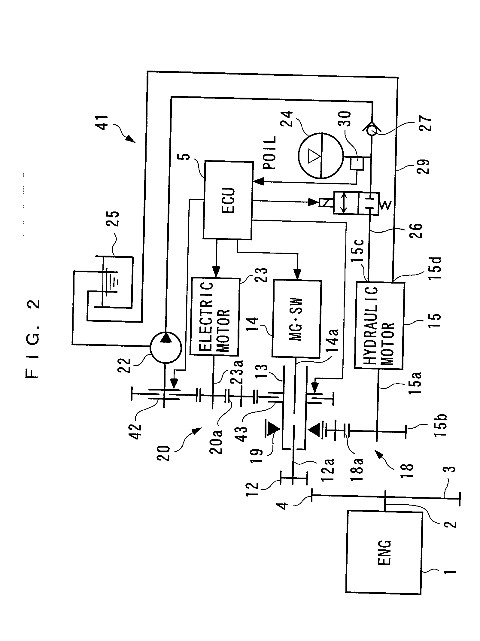
[0043] Alternatively, the electric motor 23 may be coupled to the oil pump 22 at all times, and a flow passage switching mechanism may be provided for switching a discharge flow passage of the oil pump 22 to the accumulator 24 and to the reserve tank 25. In this configuration, the oil pressure can be accumulated by driving the electric motor 23 and switching the discharge flow passage of the oil pump 22 to the accumulator 24 by the flow passage switching mechanism. On the other hand, when the engine 1 is started by the electric motor 23, a load on the electric motor 23 can be reduced by switching the discharge flow passage of the oil pump 22 to the reserve tank 25 to relieve the oil pressure. Since this configuration eliminates the expensive power switching means such as the first and second electromagnetic clutches 42, 43, reversing circuit and the like in the second embodiment for using the electric motor 23 both for accumulating the oil pressure and for starting the engine 1, thi...
PUM
 Abstract
Description
Claims
Application Information