Traction Cleat And Receptacle

Active Publication Date: 2016-07-14
PRIDE MFG CO LLC
View PDF10 Cites 3 Cited by
  • Summary
  • Abstract
  • Description
  • Claims
  • Application Information

AI Technical Summary

Benefits of technology

[0023]In some prior locking systems using the aforementioned FAST TWIST® arrangement, when rotating a cleat, the locking posts on the cleat are forced radially outward by the receptacle locking stubs or teeth and into contact with the material of the outsole in which the receptacle is embedded. Contact with the outsole material can help in the retention of the cleat in the receptacle, but it can be detrimental to the outsole, resulting in loosening the mounting of the cleat therein, and can also make the degree of cleat retention in the receptacle dependent upon the particular material used for the outsole. Another object of the invention is to prevent the locking posts on the cleat from bearing against the outsole material as the cleat is rotated in the receptacle cavity during insertion and removal of the cleat. In order to achieve this, an annular wall, or shroud, is concentrically disposed about and spaced radially outward from the outer wall of the receptacle boss. The shroud is radially positioned such that the locking posts are located radially inward of the shroud, and as the posts ride over the locking teeth and are forced outwardly, the posts make contact with the receptacle shroud, not the outsole material, so that the retention force is predictable and not dependent on different outsole materials.

Problems solved by technology

Contact with the outsole material can help in the retention of the cleat in the receptacle, but it can be detrimental to the outsole, resulting in loosening the mounting of the cleat therein, and can also make the degree of cleat retention in the receptacle dependent upon the particular material used for the outsole.

Method used


Image

  • Traction Cleat And Receptacle
  • Traction Cleat And Receptacle
  • Traction Cleat And Receptacle

Examples


Embodiment Construction

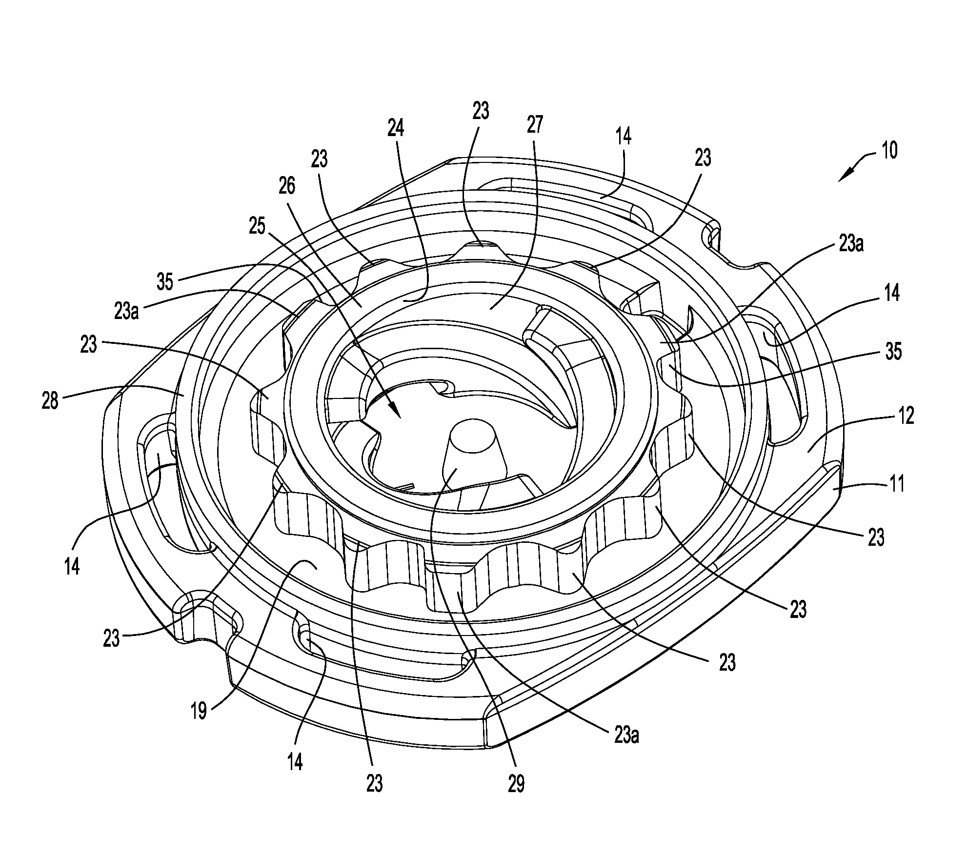
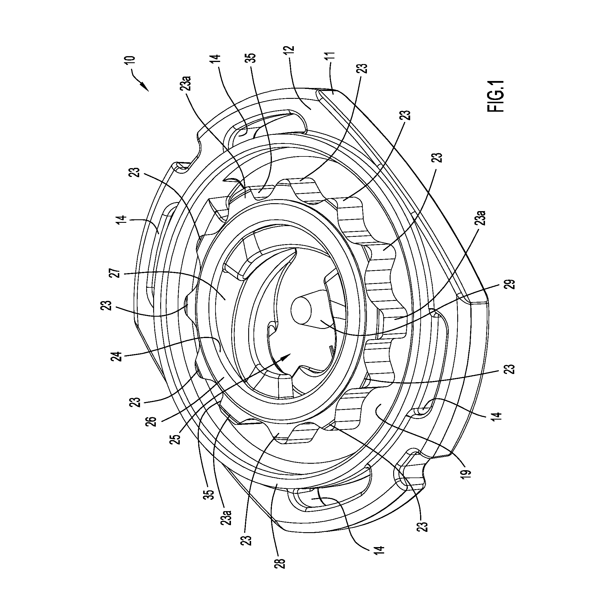
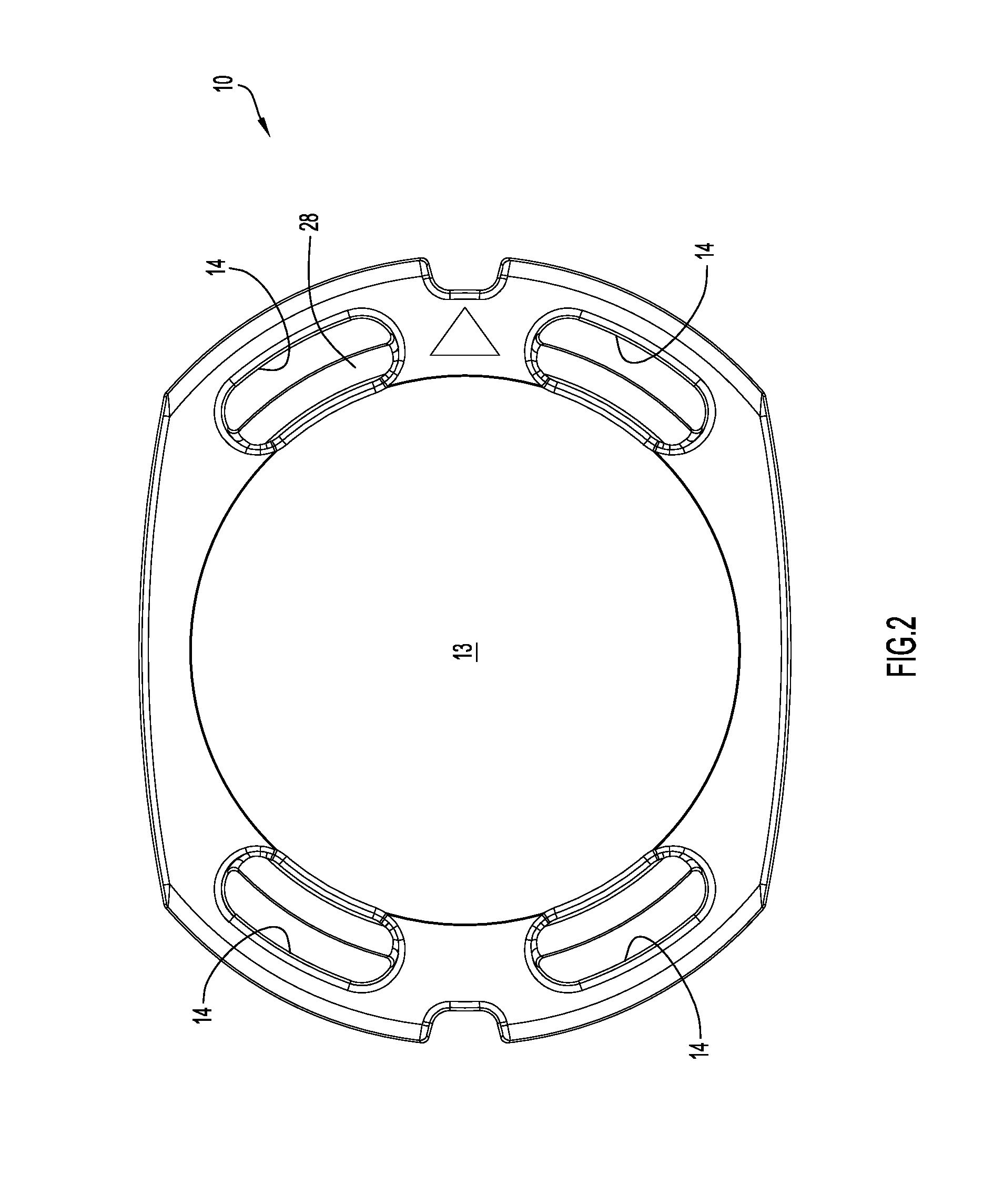
[0038]Referring to FIGS. 1-9 in greater detail, there is illustrated a receptacle 10 (FIGS. 1-5) configured to receive, engage and securely lock in place the cleat 40 (FIGS. 6-9). Receptacle 10 includes a base plate 11 having a bottom surface 12 and a top surface 13. The base plate 11, as illustrated, may be generally rectangular with slightly rounded (i.e., large radius of curvature) opposed long side edges and more rounded (i.e., smaller radius of curvature) opposed shorter side edges; however, the base plate configuration itself is not of itself a feature of the invention and can be otherwise configured, symmetrically or asymmetrically about receptacle attachment axis A. When cleat 40 is installed in receptacle 30, cleat axis B and receptacle axis A are coaxially positioned.

[0039]The radially outer portions of base 11 proximate each short side edge have two mounting slots 14 defined longitudinally therethrough (i.e., through the thickness of the base plate) for securing the recep...


PUM


Abstract

In traction cleat and receptacle system in a shoe outsole, unauthorized cleats are prevented from connection to a receptacle by a projection in the receptacle cavity and a recess in the cleat attachment stem for receiving the projection. A locking arrangement includes an annular array of twelve locking teeth on a, boss surrounding the receptacle cavity, wherein every fourth tooth has a steeper side angle to in cooperate with mating cleat locking posts. A cylindrical shroud prevents the locking posts from damaging the outsole material during cleat rotation.

Description

CROSS REFERENCE TO RELATED APPLICATION[0001]This application claims priority to U.S. Provisional Application No. 62 / 103,338, filed Jan. 14, 2015, by Pride Manufacturing Company, LLC and entitled “Improved Traction Cleat And Attachment System for Footwear”, the disclosure in which is incorporated herein in its entirety by this reference.ADDITIONAL SUBJECT MATTER INCORPORATED BY REFERENCE[0002]The subject matter disclosed and / or claimed in the following patent documents is expressly incorporated by reference herein in its entirety:[0003]U.S. Pat. No. 5,887,371 (Curley), issued Mar. 30, 1999, for “Footwear Cleat”;[0004]U.S. Pat. No. 7,107,708 (Kelly et al), issued Sep. 19, 2006, for “Studded Footwear”;[0005]U.S. Pat. No. 7,137,213 (Kelly et al), issued Nov. 21, 2006, for “Studded Footwear”;[0006]U.S. Pat. No. 8,245,422 (Krikorian et al), issued Aug. 21, 2012, for “Athletic Shoe Cleat with Dynamic Traction and Method of Making and Using Same”;[0007]U.S. Pat. No. 8,544,195 (Burt et al), ...

Claims


Application Information

Patent Timeline
Patent Type & Authority Applications(United States)
IPC IPC(8): A43C15/16
CPCA43C15/161A43C15/162A43C15/16
Inventor BURT, JOHN ROBERTSHUTTLEWORTH, LEE P.
Owner PRIDE MFG CO LLC
Why Eureka
Try Eureka