Clad Hardfacing Application on Downhole Cutting Tools

a cutting tool and hardfacing technology, applied in the field of subterranean deposits recovery, can solve problems such as tool wear and tear, and achieve the effect of reducing tool wear and tear

Inactive Publication Date: 2016-07-14
HALLIBURTON ENERGY SERVICES INC
View PDF6 Cites 3 Cited by
  • Summary
  • Abstract
  • Description
  • Claims
  • Application Information

AI Technical Summary

Problems solved by technology

While milling tools may include hardened cutters or inserts to improve cutting performance and wear resistance,

Method used


Image

  • Clad Hardfacing Application on Downhole Cutting Tools
  • Clad Hardfacing Application on Downhole Cutting Tools
  • Clad Hardfacing Application on Downhole Cutting Tools

Examples


example 7

[0058] The downhole milling tool of example 1, wherein the cutting inserts have a hardness of approximately 60 HRC.

example 8

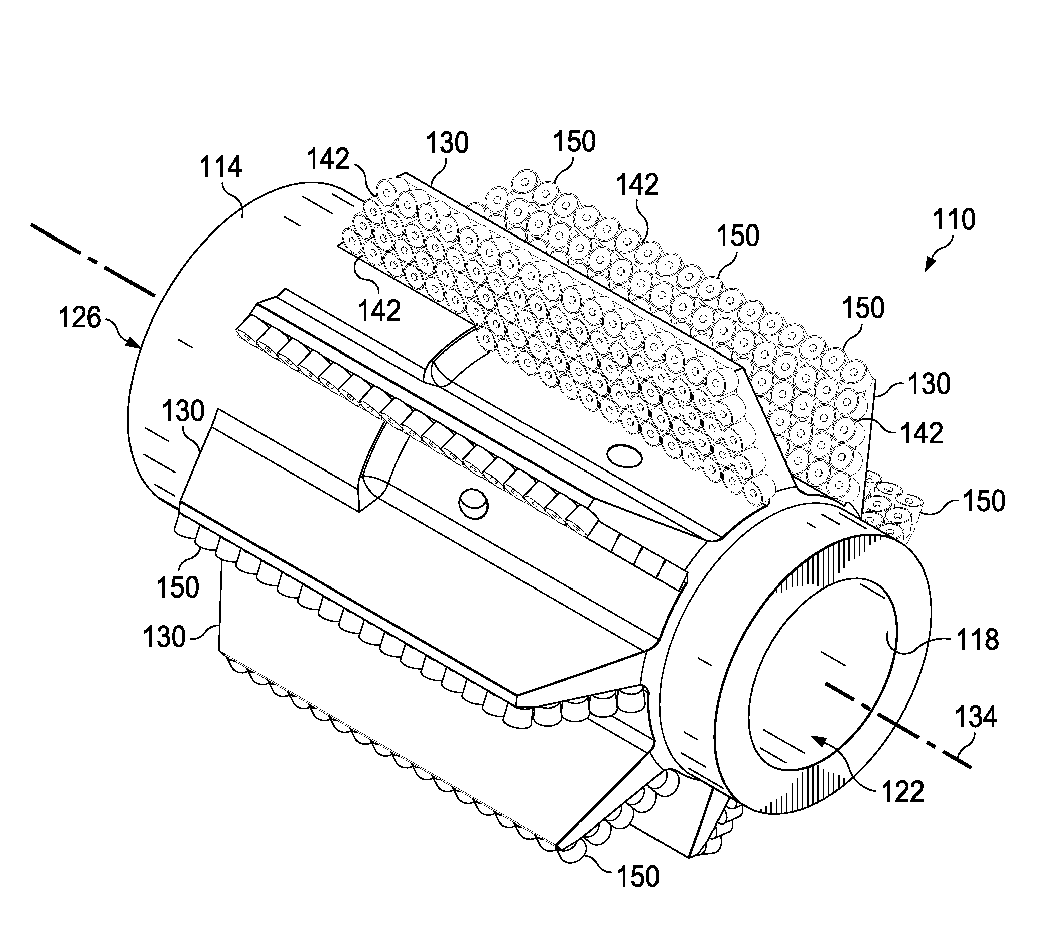
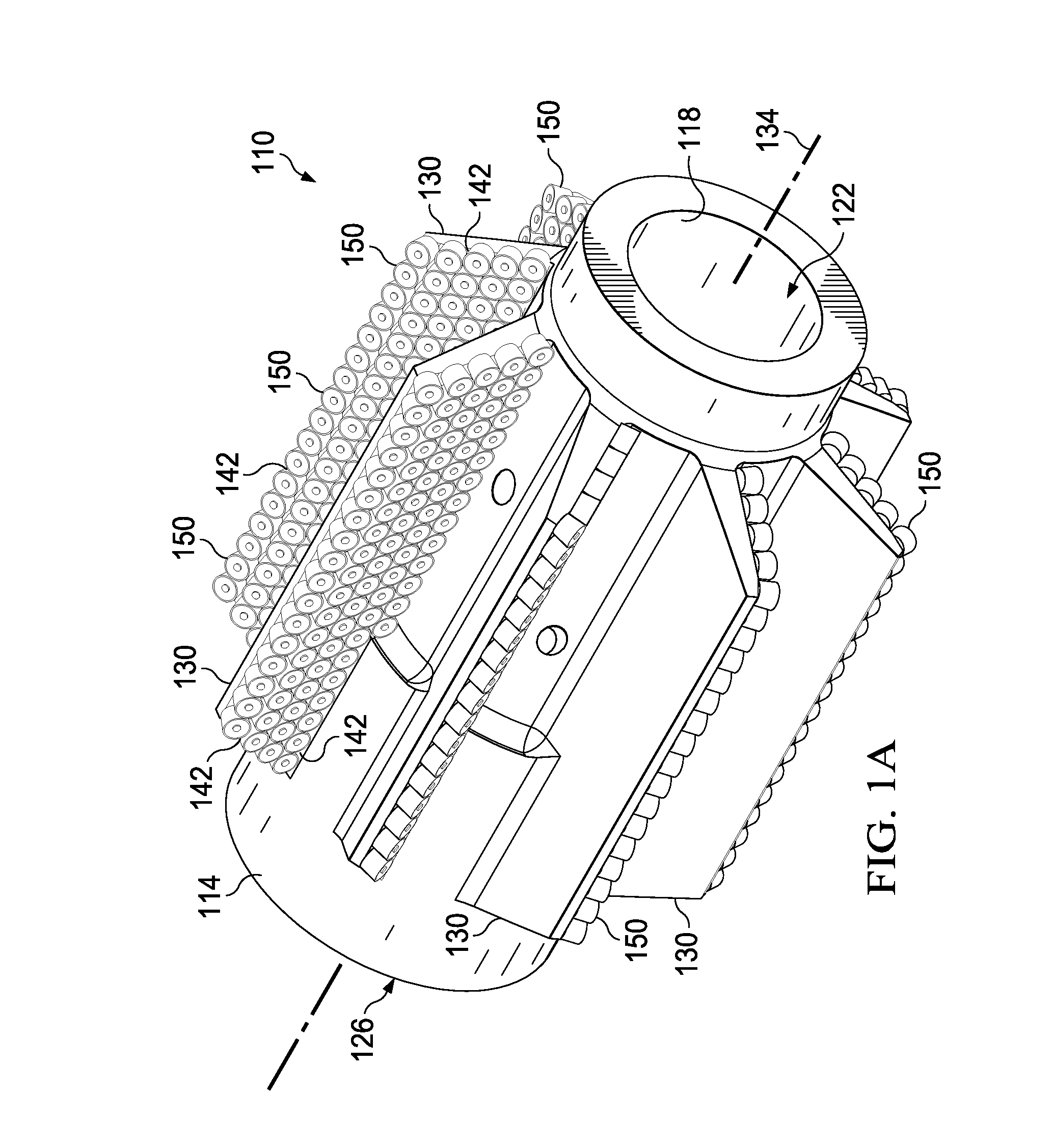
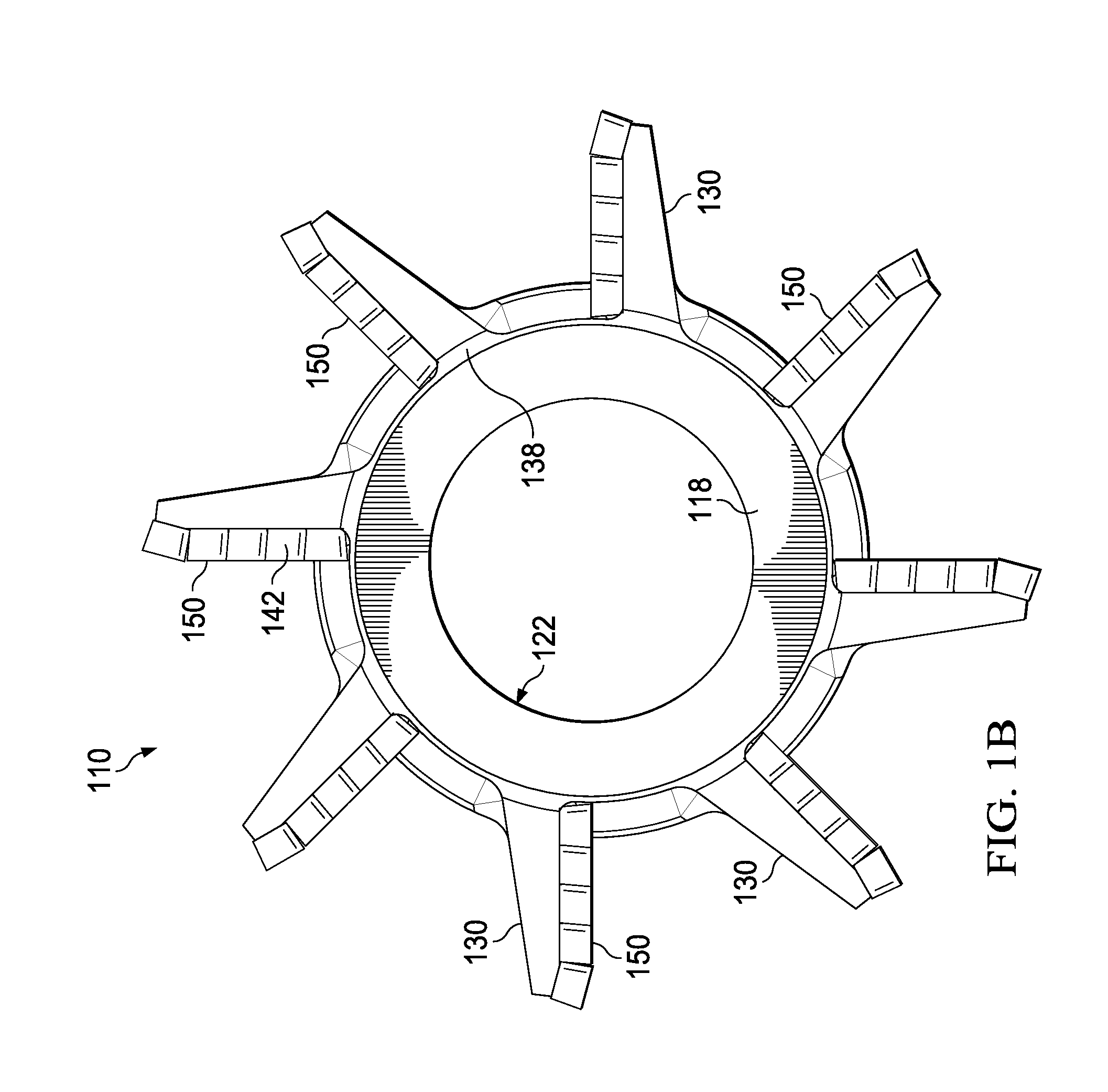
[0059] The downhole milling tool of example 1 further comprising: a plurality of cutting inserts coupled to the cladding material;[0060]wherein each cutting insert is substantially cylindrical in shape and includes a scalloped cutting surface.

[0061]Example 9. The downhole milling tool of example 1 further comprising:[0062]a plurality of cutting inserts coupled to the cladding material;[0063]wherein each cutting insert is substantially cylindrical in shape and includes a cutting surface; and[0064]wherein the cutting surface of at least one of the cutting inserts is located a distance from the mill blade greater than a distance from the mill blade to an outer surface of the cladding material.

[0065]Example 10. The downhole milling tool of example 1 further comprising:[0066]a plurality of cutting inserts coupled to the cladding material;[0067]wherein the cutting inserts are formed at least in part from tungsten carbide.

[0068]Example 11. The downhole milling tool of example 1 further com...


PUM

PropertyMeasurementUnit
Thicknessaaaaaaaaaa
Wear resistanceaaaaaaaaaa
Shapeaaaaaaaaaa

Abstract

A downhole milling tool for cutting non-geological materials in a well includes a body having an elongated and substantially cylindrical wall defining an inner passage extending through a portion of the body. The body includes a coupling end capable of being coupled to a working string to rotate the body. A plurality of blades extends radially outward from the body, and each blade extends along a length of the body. Each blade is oriented substantially parallel to a longitudinal axis of the body or is arranged in a spiral or helical configuration on the body. A laser-deposited cladding material is coupled to the plurality of blades.

Description

BACKGROUND[0001]1. Field of the Invention[0002]The present disclosure relates generally to the recovery of subterranean deposits and more specifically to methods and systems for milling materials in a well.[0003]2. Description of Related Art[0004]Wells are drilled at various depths to access and produce oil, gas, minerals, and other naturally-occurring deposits from subterranean geological formations. Hydrocarbons may be produced through a wellbore traversing the subterranean formations. The wellbore may be relatively complex and include, for example, one or more lateral branches extending at an angle from a parent or main wellbore. Forming lateral wellbores typically involves first creating a window in a casing or other metal tubing lining the main wellbore. A window mill or other milling tool may be used initiate and form the window. After the window is created, a drill bit may be passed through the window to form the lateral wellbore.[0005]In additional to milling windows for lat...

Claims


Application Information

Patent Timeline
IPC IPC(8): E21B29/00B23P15/34
CPCB23P15/34E21B29/002
Inventor GENDRE, ANDREW SCOTTRENSHAW, WILLIAM SHAUN
Owner HALLIBURTON ENERGY SERVICES INC
Why Eureka
Try Eureka