Shoe with improved structure

a technology of shoe and structure, applied in the direction of uppers, bootlegs, stiffners, etc., can solve the problems of uneven transmission of sensory information, impact, and other stresses, uneven rolling movement of the shoe, and uneven rolling movement of the foot, so as to reduce the amount of material, maintain a certain resistance to compression, and be more deformable

Inactive Publication Date: 2016-07-28
SALOMON SA
View PDF10 Cites 15 Cited by
  • Summary
  • Abstract
  • Description
  • Claims
  • Application Information

AI Technical Summary

Benefits of technology

[0024]For one of the given dimensions of the reinforcement, that is to say, for a given perimeter or for a given thickness thereof, having holes makes the reinforcement lighter. The holes, such as cavities or openings of various shapes, reduce the amount of material required to make the reinforcement.
[0025]Due to its structure, the reinforcement is also more flexible, more deformable, for example in the event of an impact against an obstacle, while nevertheless keeping a certain resistance to the compression caused by the impact. As a result, the first shell can also flex in the location where it extends opposite the reinforcing structure. In other words, providing holes in the reinforcing structure increases the surface of the shell that can be deformed in flexion. It can also be said that in the area of a reinforcing structure, the shoe upper is capable of undergoing a reversible recessed deformation, even if such deformation is less than in zones devoid of reinforcing structure. The holes enable the reinforcement to deform more easily, thereby providing more flexibility. Also, the shell can be deformed more smoothly in the area of a boundary between a zone opposite the reinforcing structure and a zone away from the reinforcing structure.
[0026]The resulting advantages include a better foot rolling movement, that is to say, a smoother and more gradual rolling movement. The difference in flexural strength between a zone of the upper provided with a reinforcing structure and a zone devoid of reinforcing structure is indeed reduced, compared to what has been observed on a shoe according to the prior art.
[0027]As a result of the foot rolling movement, the transmission of sensory information, supports, impacts, and other stresses is also more consistent and / or more accurate for a shoe according to the invention. It can be said that due to the invention, the behavior of the shoe is more precise.
[0028]Another advantage provided by the invention is improved comfort. Comfort is more homogeneous, that is to say, almost consistent, or consistent, in various locations of the shoe. In other words, comfort varies little, if at all, from a zone devoid of reinforcing structure to a zone provided with a reinforcing structure. It can be said, for example, that the boundary between two zones of the shell, one opposite the reinforcing structure and the other not opposite the reinforcing structure, remains sufficiently flexible to protect the foot of the user. This means that this boundary is not a source of injuries.
[0029]The invention also makes it possible to reduce user fatigue, because the holes, the cavities or the openings of the reinforcing structures lighten the shoe.

Problems solved by technology

But drawbacks remain, which are observed sometimes during walking, or sometimes during intense sporting activity.
A first drawback is as follows: the known shoe at least partially hinders the rolling movement of the foot, especially for running, due to the presence of one or more reinforcing structures.
It follows that the rolling movement of the foot is not sufficiently smooth, not sufficiently gradual, as it is disturbed in the area of the boundary.
It also follows that the transmission of sensory information, supports, impacts, and other stresses is slightly uneven, or slightly inaccurate.
In other words, a shoe according to the prior art lacks homogeneity in its behavior.
Another drawback is that of comfort.
Comfort is not homogeneous, that is, not consistent in various locations of the shoe.
It is particularly observed that the boundary between these zones can sometimes form a relatively non-deformable fold, which is likely to be a source of injury to the user.
Another drawback is related to inertia.
Each reinforcing structure increases the weight of the shoe, thereby causing additional fatigue for the user.

Method used


Image

  • Shoe with improved structure
  • Shoe with improved structure
  • Shoe with improved structure

Examples


first embodiment

[0042]The first embodiment to be described relates, for example, to a shoe for walking or running on level, hilly, or mountainous terrain. However, the invention is applicable to other disciplines such as those mentioned above. The term “shoe” is used here for convenience, but is not intended to limit the scope of the invention from what would be encompassed by the use of the term “footwear” or “article of footwear.”

[0043]The first embodiment is described below with reference to FIGS. 1 to 6.

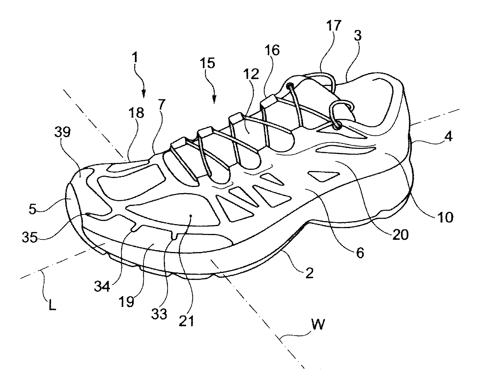
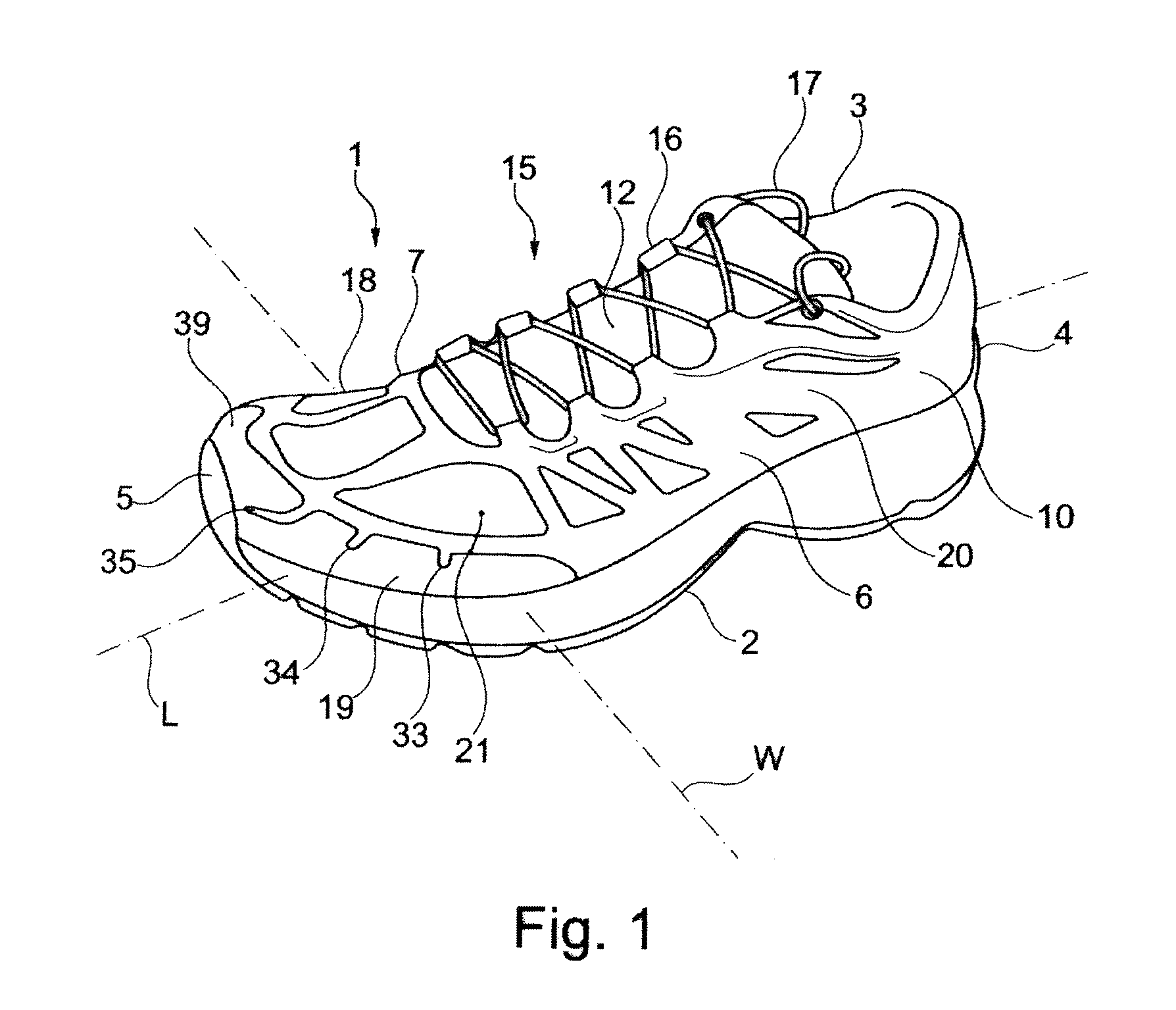
[0044]As shown in FIG. 1, a walking or running shoe 1 is provided to receive the foot of the user. The shoe 1 comprises an outer sole assembly 2 and an upper 3 arranged on the sole assembly. The shoe extends lengthwise along a longitudinal direction L, between a rear end or heel 4 and a front end or tip 5, and widthwise along a transverse direction W, between a lateral side 6 and a medial side 7.

[0045]As shown, the upper 3 includes a lower portion 10 configured to surround the foot. Alternativel...

second embodiment

[0071]The second embodiment according to FIG. 7 features a shoe 1, including an outer sole assembly 2 and an upper 3, which comprises a first shell 21, a first reinforcing structure 19, and a fitting 20. Here again, the reinforcing structure 19 is an arc-shaped toe cap 39 with a lateral arm 46, a medial arm 47 not visible in FIG. 7, and a front bridge 48. The toe cap 39 extends height-wise between a lower edge 49 and an upper edge 50.

[0072]Specific to the second embodiment of the invention, shown in FIG. 7, is the distribution of holes arranged in the reinforcement 19, or reinforcing structure. In a non-limiting manner, at least some of the holes are slits 71, 72, 73, 74 arranged away from the contour of the toe cap 39. This means that these slits do not open out in the area of the contour of the toe cap, by remaining separated from the lower edge 49 and upper edge 50. The slits here have different sizes, in particular different lengths. This makes it possible to provide flexibility...

third embodiment

[0073]The third embodiment according to FIGS. 8 to 10 also features a shoe 1, including an outer sole assembly 2 and an upper 3 that includes a first shell 21, a first reinforcing structure 19, and a fitting 20.

[0074]Specific to the third embodiment is that which relates in particular to the reinforcement 19, or reinforcing structure. In general, the reinforcing structure 19 includes a lateral wall 86 and a medial wall 87. In a non-limiting manner, each wall 86, 87 covers the first shell, in the sense that it is arranged outside of the latter. Here again, an alternative construction is that for which each wall is arranged within the first shell, but the external arrangement brings more comfort.

[0075]Similar to what has been shown for the toe cap 39, the lateral wall 86 has holes 88, and the medial wall has holes 89. This is also designed to modify the flexibility of the walls, and therefore the flexibility of the lateral 6 and medial 7 sides of the upper 3 of the shoe. The holes hav...


PUM

PropertyMeasurementUnit
thicknessaaaaaaaaaa
thicknessaaaaaaaaaa
lengthaaaaaaaaaa

Abstract

A shoe including an outer sole assembly and an upper. The shoe extends lengthwise from a rear end to a front end, widthwise between a lateral side and a medial side, and height-wise from the outer sole assembly to an upper end. The shoe further includes a first shell and a reinforcing structure arranged opposite the first shell. The reinforcing structure includes holes on at least a portion of its surface.

Description

CROSS-REFERENCE TO RELATED APPLICATION[0001]This application is based upon French Patent Application No. 15 / 00139, filed Jan. 23, 2015, the disclosure of which is hereby incorporated by reference thereto in its entirety, and the priority of which is claimed under 35 U.S.C. §119.BACKGROUND[0002]1. Field of the Invention[0003]The invention relates to a walking or sports shoe that can be used in disciplines such as running on level, hilly, or mountainous terrain, skateboarding, ball sports, cross-country or telemark skiing, snowboarding, snowshoeing, and others.[0004]2. Background Information[0005]Depending upon the intended uses, a shoe such as those of the aforementioned types must have a certain flexibility and damping capability. Flexibility must be understood as an ability to follow certain deformations of the foot of a user. This is intended, for example, to enable good foot rolling movement or tilting of the lower leg in relation to the foot when walking or running. Damping is i...

Claims


Application Information

Patent Timeline
Patent Type & Authority Applications(United States)
IPC IPC(8): A43B23/02A43B7/08
CPCA43B23/028A43B7/085A43B23/026A43B5/00A43B23/0245A43B1/0072A43B23/0235A43B23/027A43B23/081A43B23/087
Inventor BOREL, RENEGRENET, BENJAMIN
Owner SALOMON SA
Why Eureka
Try Eureka