Fluidic Module, Device and Method for Aliquoting a Liquid

a technology of fluid aliquoting and fluid module, which is applied in the direction of fluid controllers, laboratory glassware, laboratory apparatus, etc., can solve the problems of not allowing metering nor aliquoting, unable to further fluidic processing of aliquots, and only working metering, etc., to achieve the effect of reducing the rotational frequency

Active Publication Date: 2016-07-28
HAHN SCHICKARD GESELLSCHAFT FUER ANGEWANDTE FORSCHUNG EV
View PDF1 Cites 12 Cited by
  • Summary
  • Abstract
  • Description
  • Claims
  • Application Information

AI Technical Summary

Benefits of technology

[0016]Further embodiments provide a method of aliquoting a liquid by means of the above-described fluidic module. The method includes subjecting the fluidic module to such a rotational frequency that a liquid is centrifugally driven into the first measuring chamber via the first fluid inlet channel and into the second measuring chamber via the second fluid inlet channel so that a compressible medium previously present within the first measuring chamber and within the second measuring chamber is compressed by the liquid driven into the first measuring chamber and into the second measuring chamber. The method further includes reducing the rotational frequency to which the fluidic module is subjected, so that due to the reduction of the rotational frequency and to the expansion, resulting therefrom, of the compressible medium, a large part of the liquid present within the first measuring chamber is driven out of the first measuring chamber via the first fluid outlet channel, and a large part of the liquid present within the second measuring chamber is driven out of the second measuring chamber via the second fluid outlet channel.

Problems solved by technology

Metering will therefore only work when the overflow chamber is not full.
However, the fluid structure described there enables neither metering nor aliquoting.
Further fluidic processing of the aliquots is not possible, however.

Method used


Image

  • Fluidic Module, Device and Method for Aliquoting a Liquid
  • Fluidic Module, Device and Method for Aliquoting a Liquid
  • Fluidic Module, Device and Method for Aliquoting a Liquid

Examples


Embodiment Construction

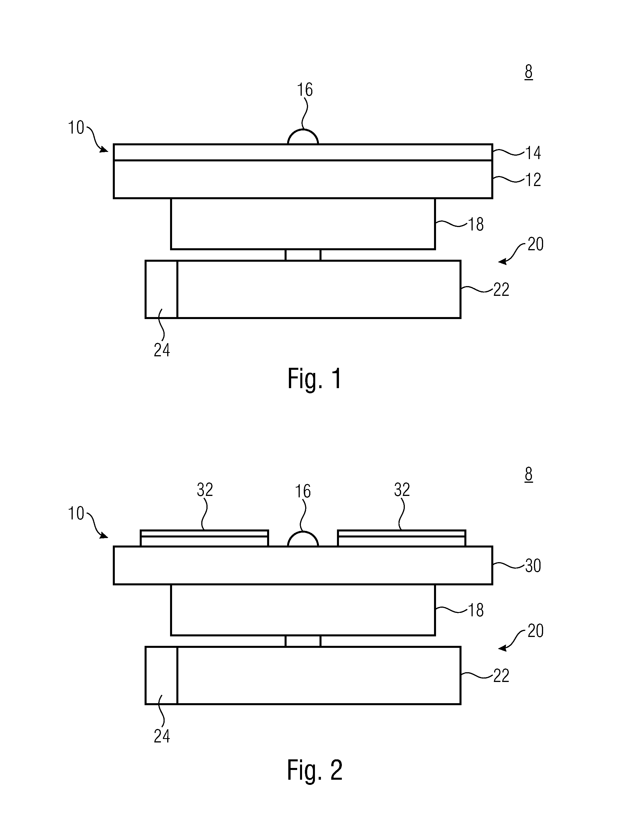
[0042]In the subsequent description of the embodiments of the invention, elements which are identical or have identical actions will be provided with identical reference numerals in the figures, so that their descriptions in the various embodiments are mutually exchangeable.

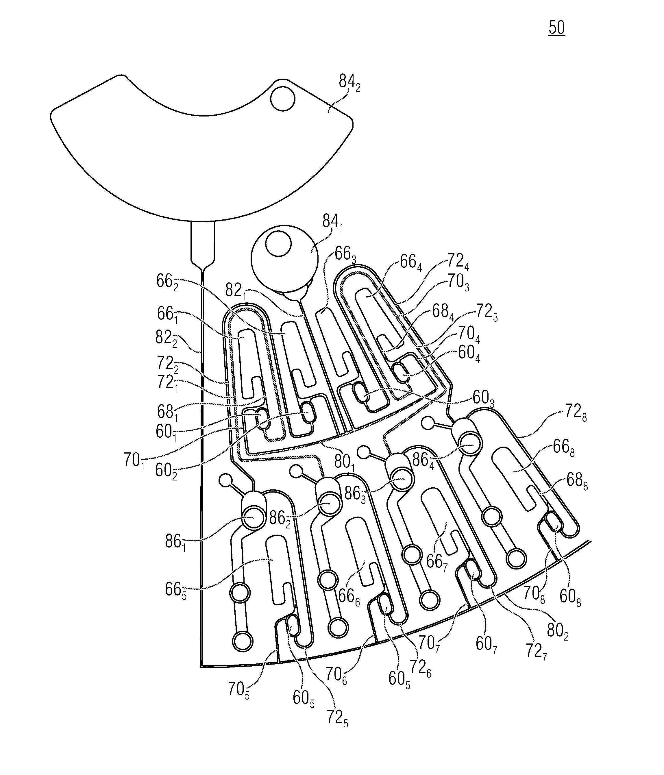
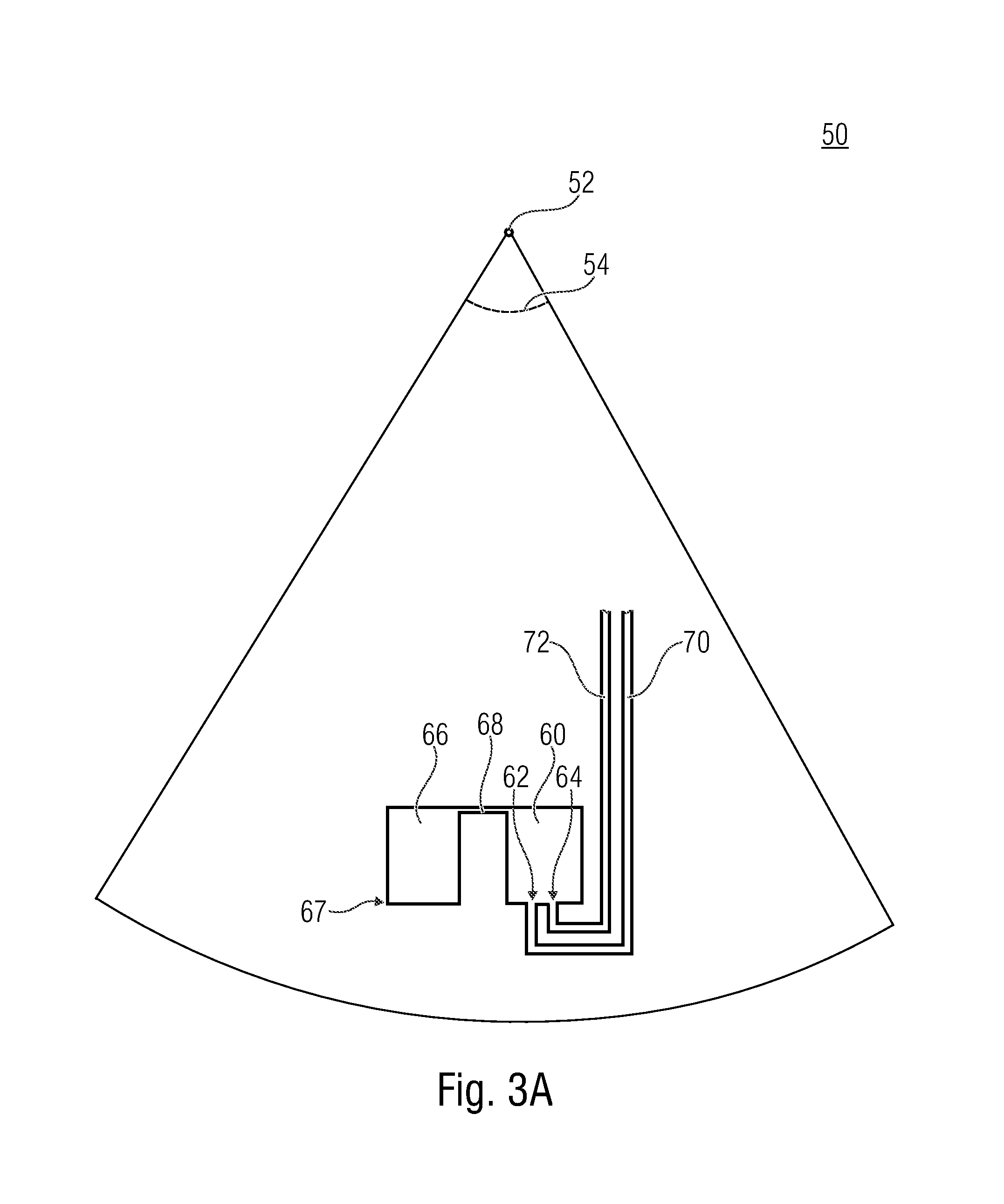
[0043]Before embodiments of the invention will be explained in more detail, it shall initially be pointed out that embodiments of the present invention are employed, in particular, in the field of centrifugal microfluidics, which is about processing of liquids within the nanoliter to milliliter ranges. Accordingly, the fluidic structures may comprise suitable dimensions within the micrometer range for handling corresponding volumes of liquid. The fluidic structures (geometric structures) as well as the pertinent methods are suitable for metering and / or aliquoting liquid within centrifuge rotors.

[0044]When the expression radial is used herein, what is meant in each case is radial in relation to the center of rotat...


PUM


Abstract

A fluidic module includes first and second measuring chambers, first and second fluid inlet channels connected to the first and second measuring chambers, respectively, and first and second fluid outlet channels connected to the first and second measuring chambers, respectively. Upon rotation of the fluidic module about a center of rotation, liquids are centrifugally driven into the first and second measuring chambers via the first and second fluid inlet channels, respectively, so that compressible media previously present within the first and second measuring chambers are compressed by the liquids driven into the first and second measuring chambers, respectively. Upon a reduction of the rotational frequency and upon an expansion, resulting therefrom, of the compressible media, the liquids present within the first and second measuring chambers are driven out of same via the first and second fluid outlet channels, respectively.

Description

CROSS-REFERENCE TO RELATED APPLICATIONS[0001]This application is a continuation of copending International Application No. PCT / EP2014 / 070018, filed Sep. 19, 2014, which claims priority from German Application No. 10 2013 219 929.5, filed Oct. 1, 2013, which are each incorporated herein in its entirety by this reference thereto.BACKGROUND OF THE INVENTION[0002]The present invention relates to a fluidic module, a device for aliquoting a liquid and a method of aliquoting a liquid. Embodiments relate to parallel-pneumatic metering and aliquoting.[0003]In centrifugal microfluidics, rotors are used for processing liquids. Corresponding rotors contain chambers for collecting liquid and channels for directing fluid. While the rotor is being subjected to centripetal acceleration, the liquid is pressed radially outward and can thus arrive at a radially outward position by directing fluid correspondingly. Centrifugal microfluidics is employed, for example, in the field of life sciences, in par...

Claims


Application Information

Patent Timeline
Patent Type & Authority Applications(United States)
IPC IPC(8): B01L3/00
CPCB01L3/50273B01L3/502715B01L3/502746B01L2400/0409B01L2200/0621B01L2400/0481B01L2300/06B01L2200/0605B01L2300/087B01L2300/0803B01L2300/0864B01L2300/0867B01L2400/0487B01L2400/084
Inventor SCHWEMMER, FRANKZEHNLE, STEFFENPAUST, NILSKOSSE, PIERRE DOMINIQUEMARK, DANIEL
Owner HAHN SCHICKARD GESELLSCHAFT FUER ANGEWANDTE FORSCHUNG EV
Why Eureka
Try Eureka