Pile, pile head and connector therefor

a technology of connectors and piles, applied in the direction of bulkheads/piles, foundation engineering, construction, etc., can solve the problems of screw piles that do not offer an adjustment of the height of the platform, screw piles that do not offer lateral movement of bolts, and screw piles of the art tend to be unsatisfactory, so as to prevent unwanted movement

Active Publication Date: 2016-07-28
GOLIATHTECH
View PDF2 Cites 22 Cited by
  • Summary
  • Abstract
  • Description
  • Claims
  • Application Information

AI Technical Summary

Benefits of technology

[0011]a first fastening means for removably fastening the mounting portion of the pile head to the top end of the pile body and preventing unwanted movement of the pile head relative to the pile body, along the longitudinal axis.

Problems solved by technology

In such configurations, the screw piles do not offer an adjustment of the height of the platform once the screw pile is installed which may, in some instances, require further positioning of the entire screw pile relative to the ground.
Since the installation of screw piles generally requires the use of relatively heavy equipment, such adjustment may be burdensome and provide unsatisfactory results.
Therefore, when the screw piles offer adjustment, the bolt tend to be loose in the bore and some lateral movement of the bolt is susceptible to occur relative to the adaptor (see FIG. 1), which lateral movement is transferred to the plate and the structure mounted thereto.
Further the screw piles of the art tend not to be satisfactory because they are not adapted to prevent upward movement of the structure relative to the screw pile (e.g. in instances of high winds lifting structures such as decks) because the adaptor is maintained into position of the pile body by gravity.
This, however, is difficult to achieve on the field and, alternatively, makes the installation of the pile more complex if the platform is already attached to the pile at the time of installation.

Method used


Image

  • Pile, pile head and connector therefor
  • Pile, pile head and connector therefor
  • Pile, pile head and connector therefor

Examples


Embodiment Construction

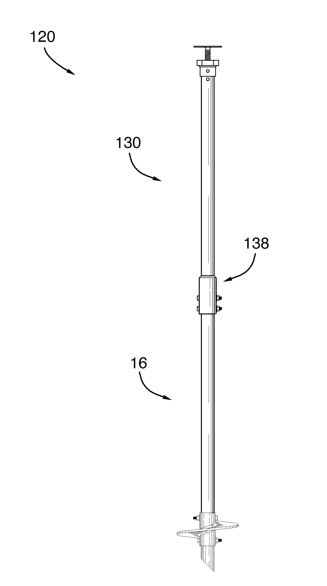
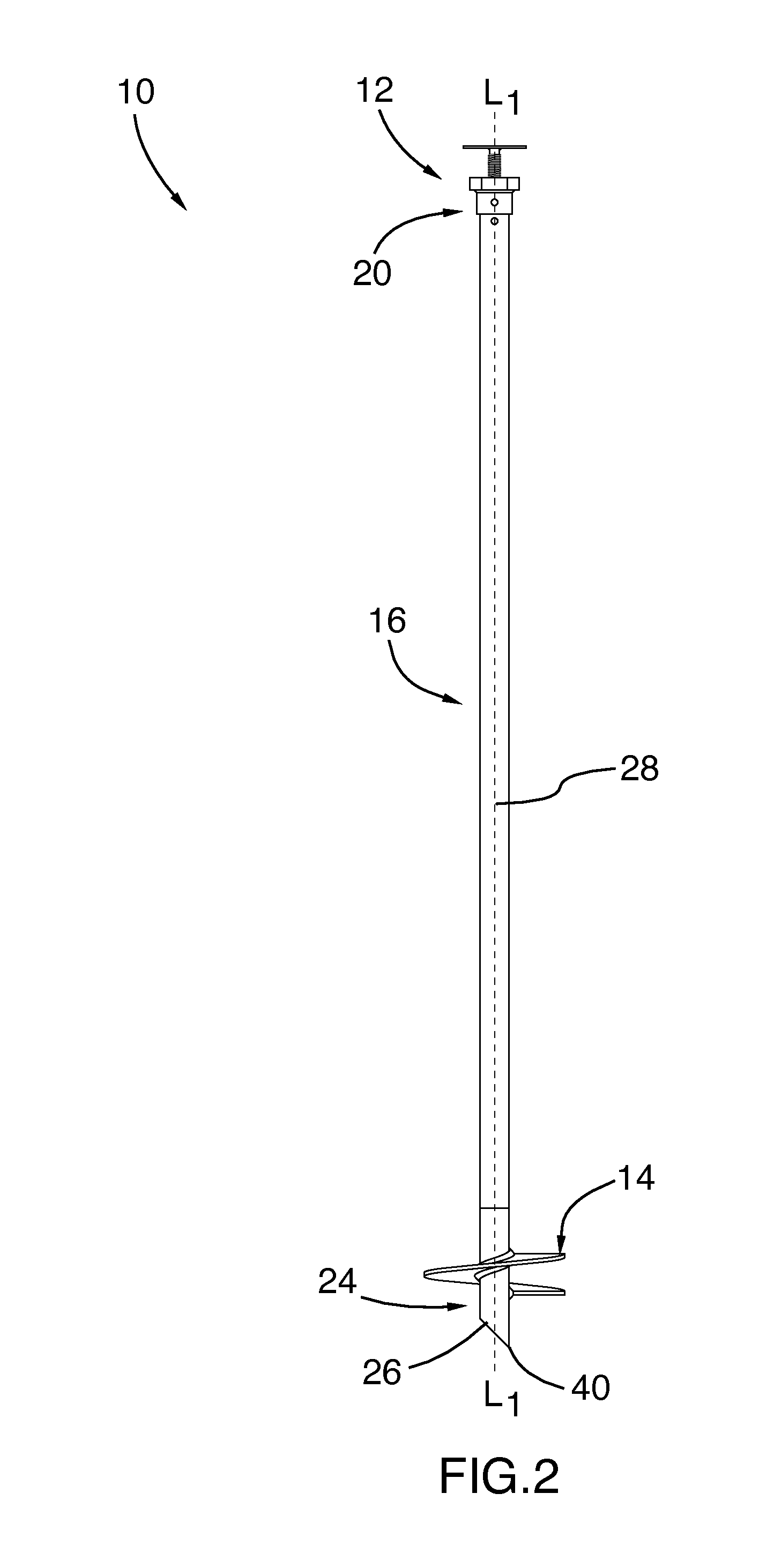
[0066]Referring to FIGS. 2 to 4, a screw pile 10 having one embodiment of pile head 12 will be described. The screw pile 10 may be used alone or in conjunction with other similar screw piles 10 to support a beam or a structure such as a fence, a deck, a sun room, a cart port, a cabin and the like. As it will become apparent below, the configuration of the pile head 12 can be adapted to securely receive such beam or structure. As it will become apparent below, the screw pile 10 could also be used horizontally or angularly, for instance to support wall or reinforce cliffs that are susceptible to collapse. The person skilled in the art will understand that in such a case, the movement of pile head 12 relative to the pile body 16, along the longitudinal axis L1 thereof, is not vertical but rather horizontal or inclined relative to the horizontal.

[0067]In the illustrated embodiment, the screw pile 10 comprises an elongated cylindrical and hollow pile body 16 having a top end 20 terminati...


PUM


Abstract

A pile head for a screw pile having a top end and a longitudinal axis is provided. The pile head comprises a mounting portion engaging the pile and an extendable portion movably mounted to the mounting portion. The extendable portion is movable relative to the mounting portion, along the longitudinal axis. A first fastening means is used to removably fasten the mounting portion of the pile head to the top end of the pile and preventing unwanted movement of the pile head relative to the pile, along the longitudinal axis. A screw pile, a removable helical member and a body extension for a screw pile are also provided.

Description

CROSS-REFERENCE[0001]Priority is hereby claimed from previously filed U.S. provisional patent application No. 61 / 868,773, filed Aug. 22, 2013, the contents of which are hereby incorporated by reference.BACKGROUND[0002]The use of screw piles is an alternative to the use of concrete foundations in different residential, commercial, recreational or agricultural applications. Resembling large screws, screw piles are typically installed deep into the ground to support structures such as decks, sun rooms, cart ports and the like.[0003]A screw pile generally includes an elongated cylindrical, hollow pile body having the general configuration of a metal pipe. The hollow pile body comprises an upper end and a lower end to which is welded a helical member, which is used to screw the pile into the ground and to provide vertical stability once the screw pile is properly installed. Mounted to the upper end of the pile body is a pile head configured to receive or support a structure.[0004]Various...

Claims


Application Information

Patent Timeline
Patent Type & Authority Applications(United States)
IPC IPC(8): E02D5/56E02D5/22
CPCE02D5/56E02D2600/20E02D5/223E02D5/526E02D35/005E02D2200/1671E02D2200/1685
Inventor REUSING, JULIAN L.PUDAR, PREDRAG
Owner GOLIATHTECH
Why Eureka
Try Eureka