Turbine bucket for control of wheelspace purge air

a technology of purge air and gas turbine, which is applied in the direction of mechanical equipment, machine/engine, leakage prevention, etc., can solve the problems of large mixing loss and most gas turbines exhibiting significant amount of purge air escap

Active Publication Date: 2016-07-28
GENERAL ELECTRIC CO
View PDF5 Cites 5 Cited by
  • Summary
  • Abstract
  • Description
  • Claims
  • Application Information

AI Technical Summary

Problems solved by technology

Nevertheless, most gas turbines exhibit a significant amount of purge air escape into the hot gas flowpath.
The consequent mixing of cooler purge air with the hot gas flowpath results in large mixing losses, due not only to the differences in temperature but also to the differences in flow direction or swirl of the purge air and hot gasses.

Method used


Image

  • Turbine bucket for control of wheelspace purge air
  • Turbine bucket for control of wheelspace purge air
  • Turbine bucket for control of wheelspace purge air

Examples


Embodiment Construction

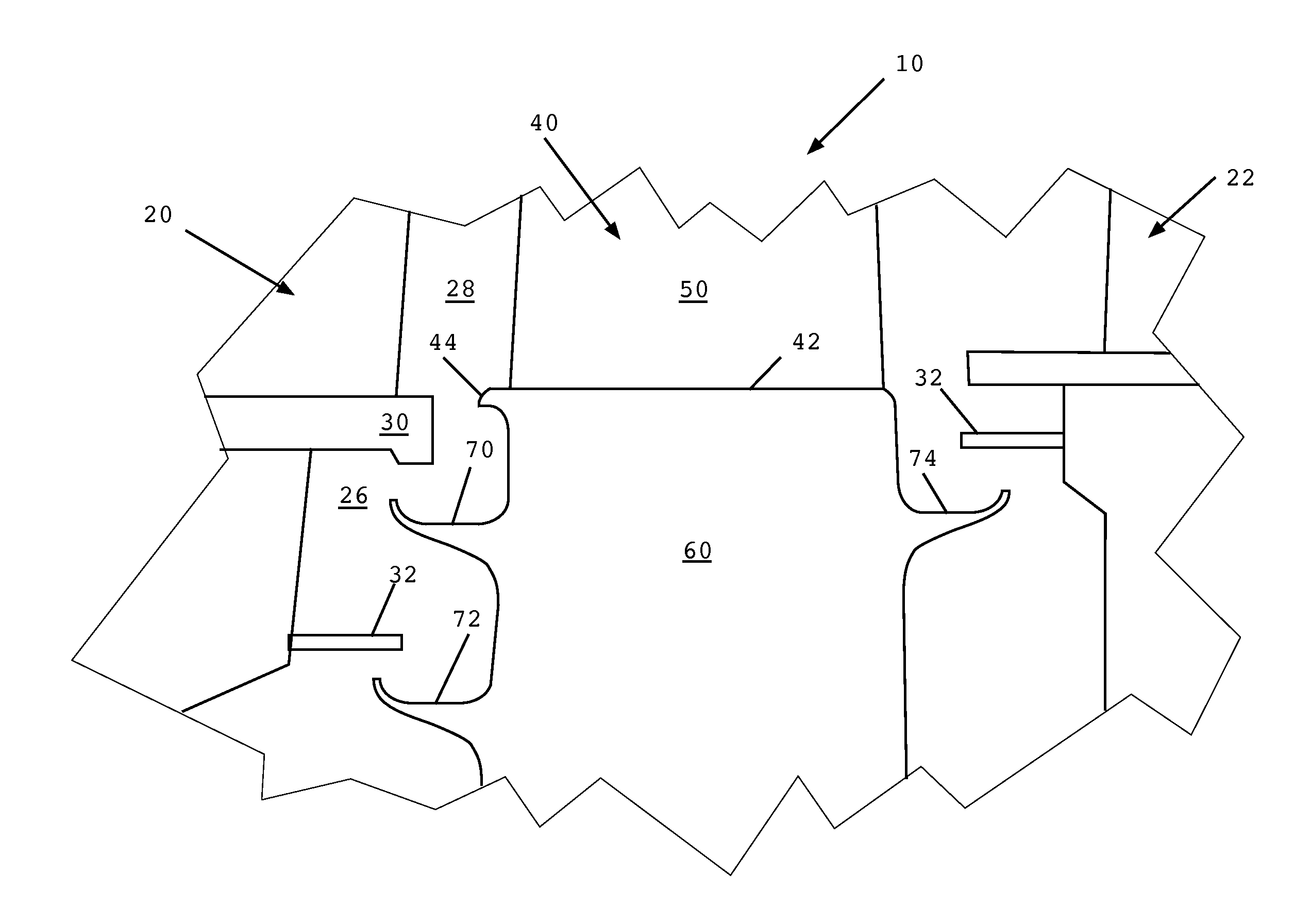
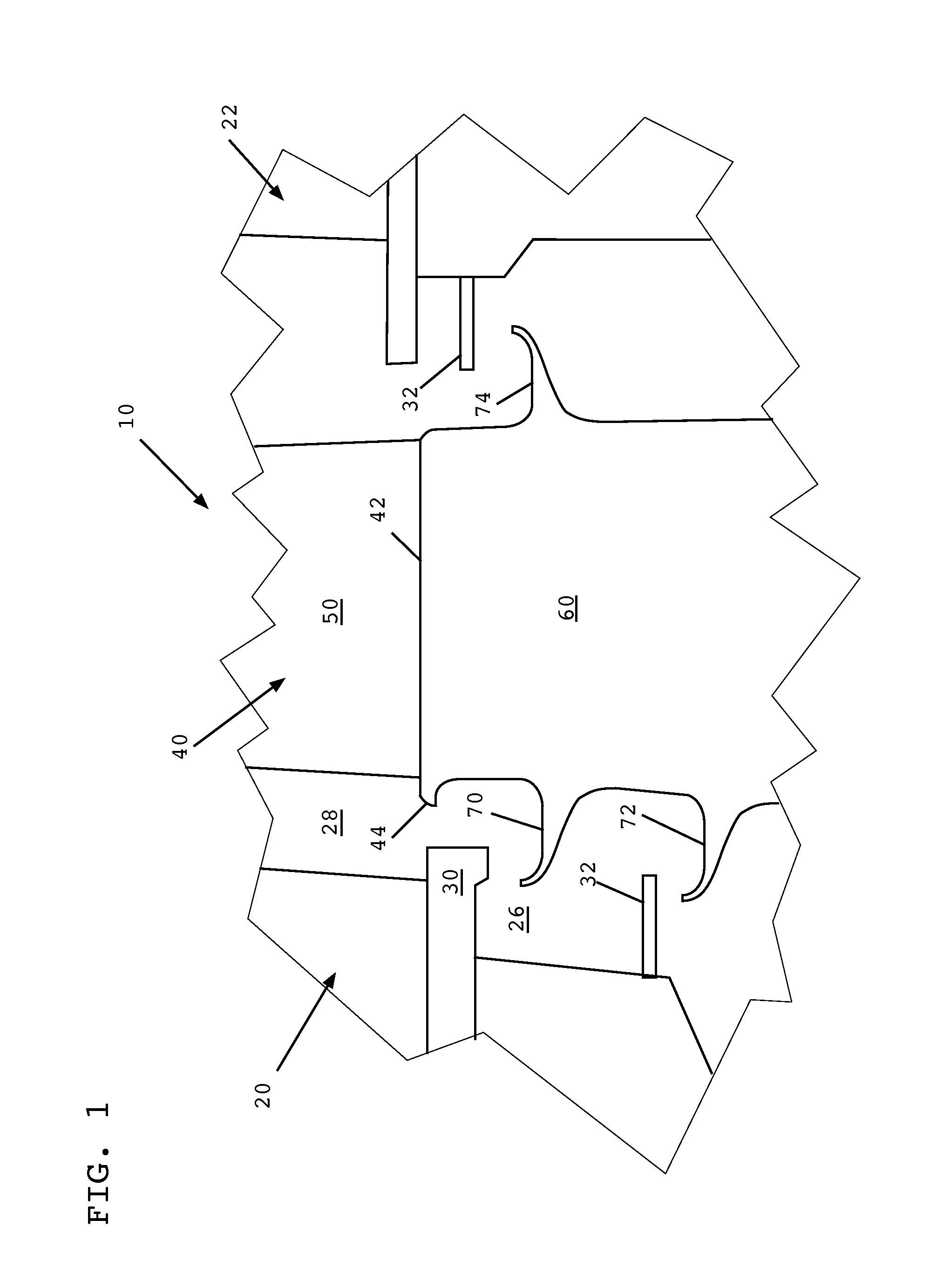
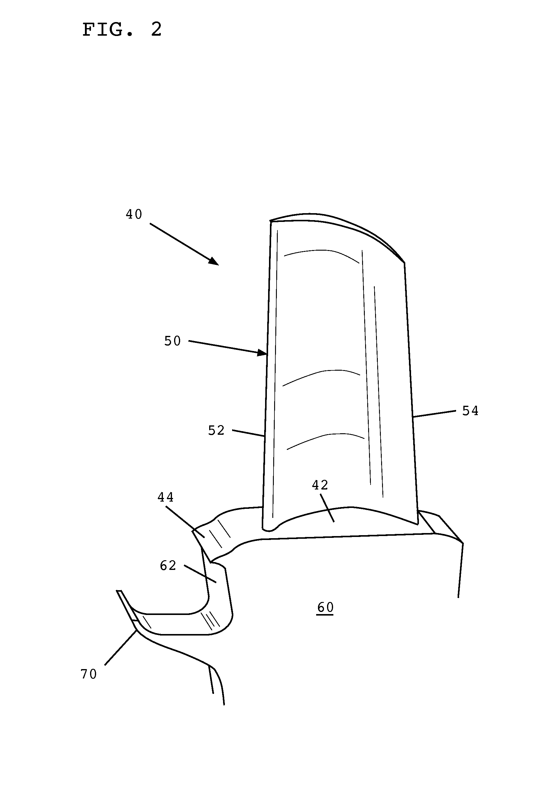
[0026]Turning now to the drawings, FIG. 1 shows a schematic cross-sectional view of a portion of a gas turbine 10 including a bucket 40 disposed between a first stage nozzle 20 and a second stage nozzle 22. Bucket 40 extends radially outward from an axially extending rotor (not shown), as will be recognized by one skilled in the art. Bucket 40 comprises a substantially planar platform 42, an airfoil extending radially outward from platform 42, and a shank portion 60 extending radially inward from platform 42.

[0027]Shank portion 60 includes a pair of angel wing seals 70, 72 extending axially outward toward first stage nozzle 20 and an angel wing seal 74 extending axially outward toward second stage nozzle 22. It should be understood that differing numbers and arrangements of angel wing seals are possible and within the scope of the invention. The number and arrangement of angel wing seals described herein are provided merely for purposes of illustration.

[0028]As can be seen in FIG. 1...


PUM


Abstract

Embodiments of the invention relate generally to rotary machines and, more particularly, to the control of wheel space purge flow in gas turbines. In one embodiment, the invention provides a turbine bucket comprising: a platform portion; an airfoil extending radially outward from the platform portion; a shank portion extending radially inward from the platform portion; at least one angel wing extending axially from a face of the shank portion; a platform lip extending axially from the platform portion, the platform lip disposed radially outward from the at least one angel wing; and a plurality of turbulators disposed along and extending outward from the face of the shank portion between the platform lip and the at least one angel wing.

Description

BACKGROUND OF THE INVENTION[0001]Embodiments of the invention relate generally to rotary machines and, more particularly, to the control of wheel space purge air in gas turbines.[0002]As is known in the art, gas turbines employ rows of buckets on the wheels / disks of a rotor assembly, which alternate with rows of stationary vanes on a stator or nozzle assembly. These alternating rows extend axially along the rotor and stator and allow combustion gasses to turn the rotor as the combustion gasses flow therethrough.[0003]Axial / radial openings at the interface between rotating buckets and stationary nozzles can allow hot combustion gasses to exit the hot gas path and radially enter the intervening wheelspace between bucket rows. To limit such incursion of hot gasses, the bucket structures typically employ axially-projecting angel wings, which cooperate with discourager members extending axially from an adjacent stator or nozzle. These angel wings and discourager members overlap but do no...

Claims


Application Information

Patent Timeline
Patent Type & Authority Applications(United States)
IPC IPC(8): F01D11/00
CPCF01D11/001
Inventor CHOUHAN, ROHITBHAUMIK, SOUMYIK KUMAR
Owner GENERAL ELECTRIC CO
Why Eureka
Try Eureka