Compact Shielded Automotive Radar Module and Method

a radar module and shielding technology, applied in the field of automotive radar devices and methods, can solve the problems of cumbersome devices, difficult to provide shielding to protect against electromagnetic interference (emi), and difficulty in maintaining sufficient rf isolation between active components of such devices

Active Publication Date: 2016-07-28
VEONEER US LLC
View PDF7 Cites 26 Cited by
  • Summary
  • Abstract
  • Description
  • Claims
  • Application Information

AI Technical Summary

Benefits of technology

[0006]According to one aspect, an automobile radar module is provided. The module includes a housing and a printed circuit board (PCB) mounted in the housing, the PCB having a first side on which radio frequency (RF) electronic components are mounted and a second side on which digital electronic components are mounted. An electromagnetic interference (EMI) shield is mounted over the first side of the PCB, and a radome is mounted over the EMI shield. The EMI shield comprises at least one aperture through a primary surface of the EMI shield, the at least one aperture exposing at least a portion of the RF co

Problems solved by technology

A sensor module using the two-PCB design typically requires connectors and cabling to connect the two PCBs, such that shielding to protect against electromagnetic interference (EMI) is d

Method used


Image

  • Compact Shielded Automotive Radar Module and Method
  • Compact Shielded Automotive Radar Module and Method
  • Compact Shielded Automotive Radar Module and Method

Examples


Embodiment Construction

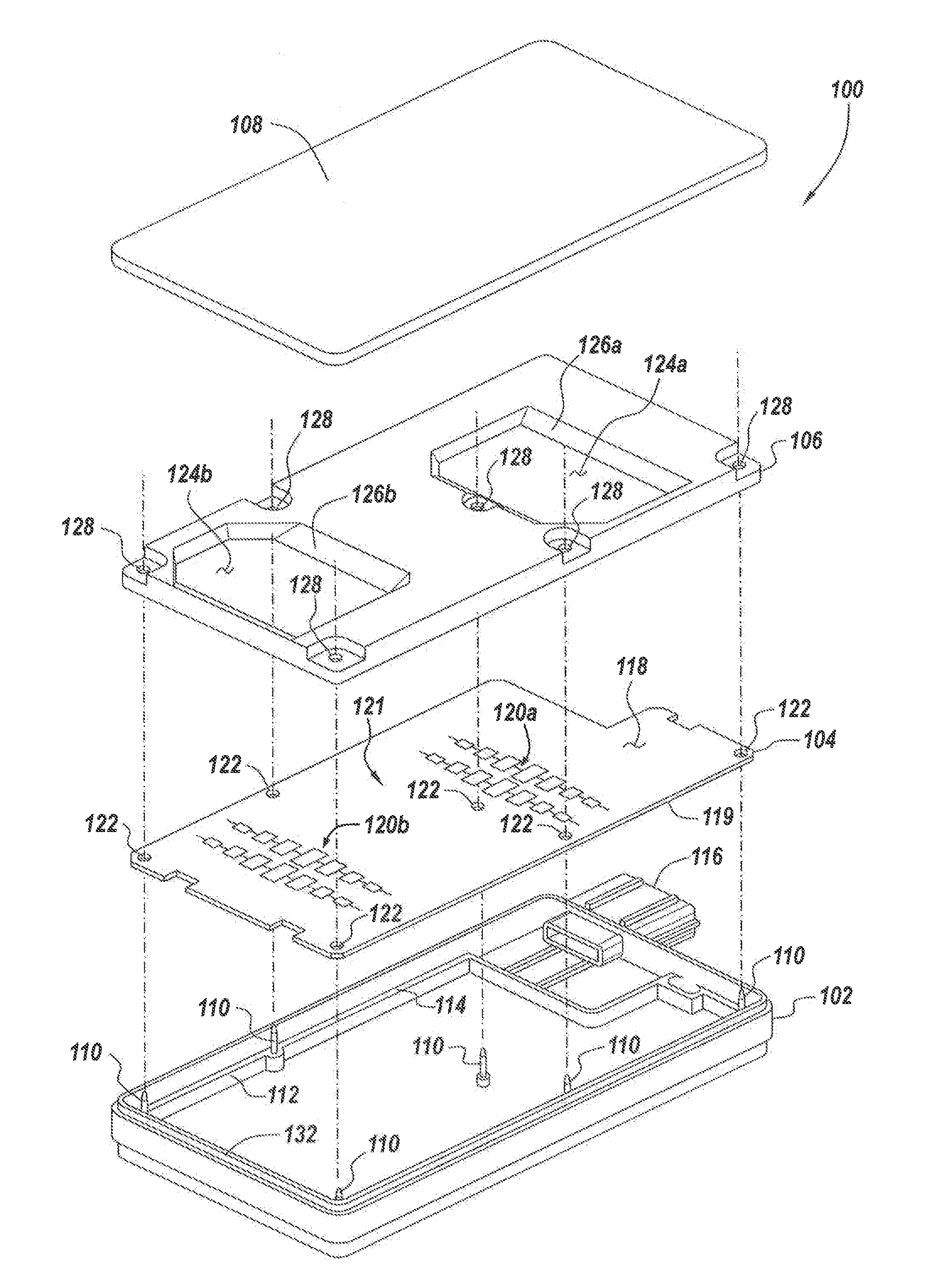
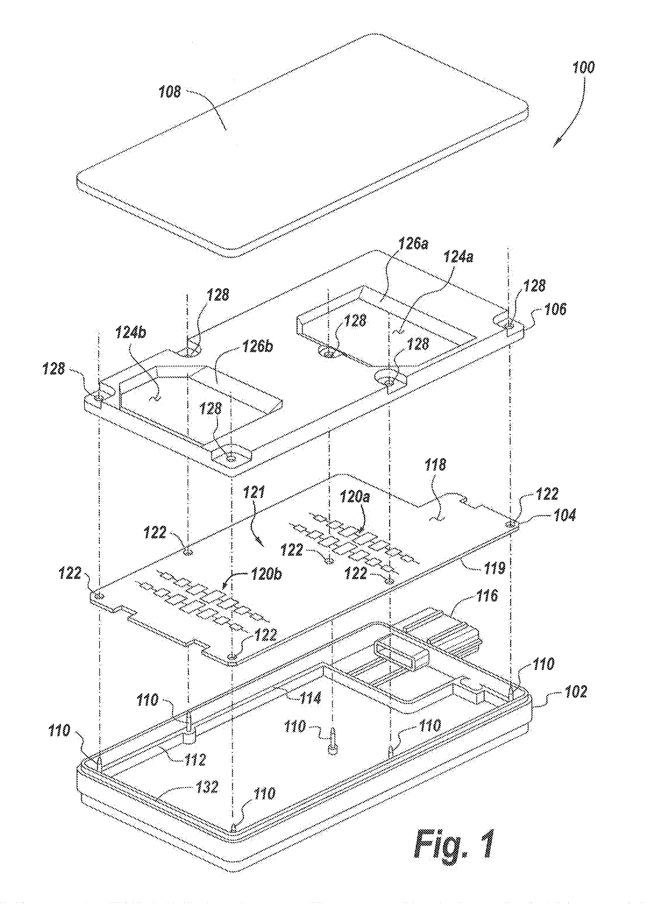
[0029]FIGS. 1 and 2 include schematic exploded perspective views of an automobile radar module taken from different view perspectives. Specifically, FIG. 1 includes a schematic exploded perspective view of an automobile radar module, taken from above the module, according to some exemplary embodiments; and FIG. 2 includes another schematic exploded perspective view of the automobile radar module, taken from below the module, according to some exemplary embodiments.

[0030]Referring to FIGS. 1 and 2, automobile radar module 100 includes a housing or base 102 in which components of module 100 are mounted. Module 100 also includes a PCB 104, an EMI shield 106 and a radome or cover 108 disposed in a stacked configuration and assembled together. FIG. 3 includes a schematic top view of housing 102, according to some exemplary embodiments. Referring to FIGS. 1 through 3, housing 102 can be made of plastic and can be formed by injection molding. Housing 102 can be formed integrally with a shr...


PUM


Abstract

An automobile radar module and method include a PCB having a first side on which RF electronic components are mounted and a second side on which digital electronic components are mounted. An EMI shield is mounted over the first side of the PCB, and a radome is mounted over the EMI shield. The EMI shield comprises an aperture exposing RF components on the first side of the PCB. The radome comprises a protrusion which protrudes into the aperture in the EMI shield. The protrusion and sidewalls of the aperture define a shielded region above the RF components on the first side of the PCB. The sidewalls extend at an acute angle with respect to a plane of the primary surface of the EMI shield, the acute angle being selected based on operational parameters of the radar module such that a predetermined shielding performance is realized.

Description

RELATED APPLICATION[0001]This application claims the benefit of U.S. Provisional Patent Application No. 61 / 885,364, filed on Oct. 1, 2013, the entire contents of which are incorporated herein by reference.BACKGROUND[0002]1. Technical Field[0003]This disclosure is related to automotive radar devices and methods, and, more particularly, to automotive radar devices and methods having improved EMI shielding.[0004]2. Discussion of Related Art[0005]Existing radar sensor modules generally include two separate printed circuit boards (PCBs). One of the PCBs typically includes components dedicated to handling radio frequency (RF) radar signals, and the other PCB typically includes components dedicated to handling digital signal processing (DSP) tasks. A sensor module using the two-PCB design typically requires connectors and cabling to connect the two PCBs, such that shielding to protect against electromagnetic interference (EMI) is difficult to provide. It is also difficult to maintain suffi...

Claims


Application Information

Patent Timeline
IPC IPC(8): H01Q1/32G01S13/93H01Q21/00H01Q21/06H01Q1/42H01Q1/52G01S13/931
CPCH01Q1/3233H01Q1/42H01Q1/526G01S2007/028H01Q21/065G01S13/931G01S2007/027H01Q21/0075G01S7/032G01S7/028G01S7/027
Inventor LEUNG, RICHARDDEMERSSEMAN, BERNARD
Owner VEONEER US LLC
Why Eureka
Try Eureka