
LED tube lamp

Active Publication Date: 2016-07-28
JIAXING SUPER LIGHTING ELECTRIC APPLIANCE
View PDF2 Cites 59 Cited by
  • Summary
  • Abstract
  • Description
  • Claims
  • Application Information

AI Technical Summary

Benefits of technology

The present invention provides an LED tube lamp, with a unique circuit design that filters and controls the external driving signal, allowing for precise control of the LED lighting module. The lamp is also compatible with various ballasts, making it easy to install and modify for different applications. The technical effect of this invention is to provide a highly efficient and precise LED tube lamp that is easy to control and modify.

Problems solved by technology

For example, the driving signals for the florescent lamp may not be DC signals and may have significant different frequencies and voltages, and so they often cannot be used to drive the LED only by a rectification circuit.

Method used


Image

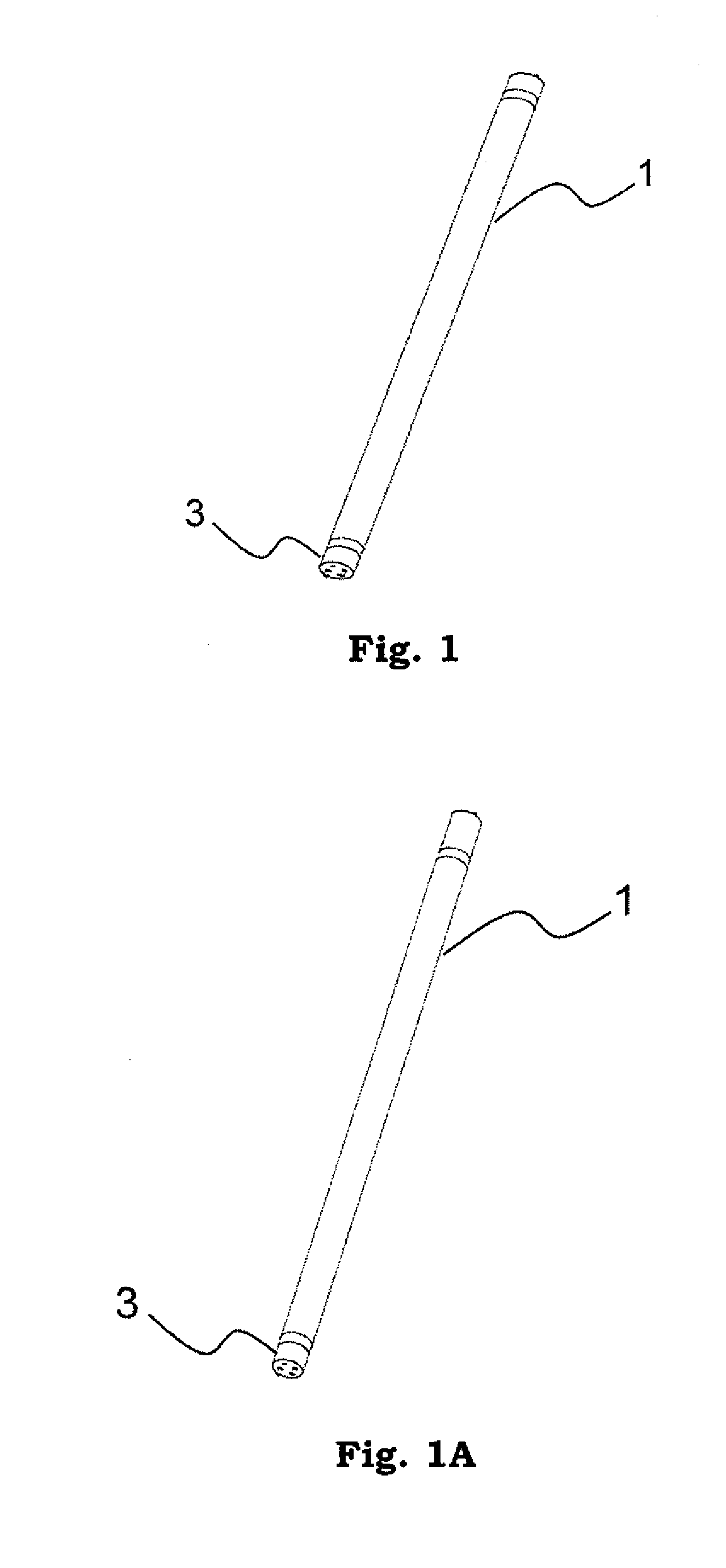
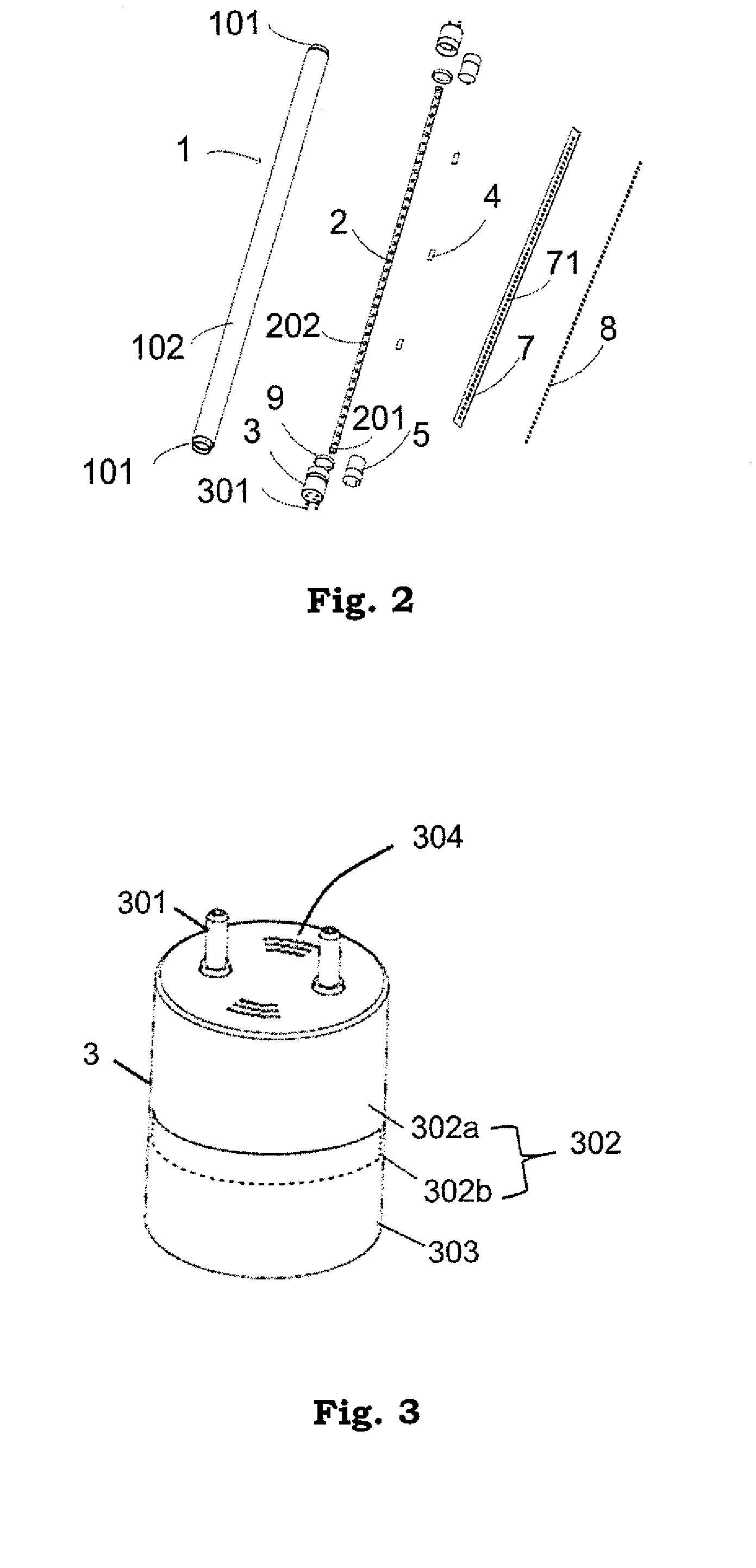
  • LED tube lamp
  • LED tube lamp
  • LED tube lamp

Examples


Embodiment Construction

[0118]The present disclosure now will be described more fully hereinafter with reference to the accompanying drawings, in which various embodiments are shown. The invention may, however, be embodied in many different forms and should not be construed as limited to the example embodiments set forth herein. These example embodiments are just that—examples—and many implementations and variations are possible that do not require the details provided herein. It should also be emphasized that the disclosure provides details of alternative examples, but such listing of alternatives is not exhaustive. Furthermore, any consistency of detail between various examples should not be interpreted as requiring such detail—it is impracticable to list every possible variation for every feature described herein. The language of the claims should be referenced in determining the requirements of the invention.

[0119]In the drawings, the size and relative sizes of layers and regions may be exaggerated for...


PUM


Abstract

An LED tube lamp includes a first rectifying circuit, a filter circuit, an LED lighting module, and a ballast-compatible circuit. The first rectifying circuit is coupled to a first pin and second pin and is configured to rectify an external driving signal transmitted from the first pin and / or the second pin. The filter circuit is coupled to the first rectifying circuit and is configured to filter the rectified signal by the first rectifying circuit. The LED lighting module is coupled to the filter circuit and receives the filtered signal by the filter circuit to light. The ballast-compatible circuit has two ballast-compatible circuit terminals coupled to the first rectifying circuit and is configured to control the LED tube lamp to light or stop lighting according to the external driving signal.

Description

CROSS-REFERENCE TO RELATED APPLICATIONS[0001]The present application is a Continuation-In-Part application of U.S. patent application Ser. No. 14 / 865,387, filed Sep. 25, 2015, the contents of which are incorporated herein by reference in their entirety, and which claims the benefit of priority under 35 U.S.C. §119 to the following Chinese Patent Applications, filed with the State Intellectual Property Office (SIPO), the contents of each of which are incorporated herein by reference in their entirety: CN 201410507660.9 filed on Sep. 28, 2014; CN 201410508899.8 filed on Sep. 28, 2014; CN 201410623355.6 filed on Nov. 6, 2014; CN 201410734425.5 filed on Dec. 5, 2014; CN 201510075925.7 filed on Feb. 12, 2015; CN201510104823.3 filed Mar. 10, 2015; CN201510133689.x filed Mar. 25, 2015; CN201510134586.5 filed Mar. 26, 2015; CN201510136796.8 filed Mar. 27, 2015; CN201510155807.7 filed Apr. 3, 2015; CN201510173861.4 filed Apr. 14, 2015; CN201510193980.6 filed Apr. 22, 2015; CN 201510259151.3 ...

Claims


Application Information

Patent Timeline
IPC IPC(8): H05B33/08F21K99/00H05B44/00
CPCH05B33/089F21Y2103/003F21K9/17H05B33/0809F21V29/83F21K9/27F21Y2103/10F21Y2115/10F21V7/005F21V23/02H05B45/50H05B45/36H05B45/38H05B45/345H05B45/375H05B45/32H05B45/31H05B45/59
Inventor XIONG, AIMINGLIU, XINTONGWU, XIAOJIA
Owner JIAXING SUPER LIGHTING ELECTRIC APPLIANCE
Features
  • Generate Ideas
  • Intellectual Property
  • Life Sciences
  • Materials
  • Tech Scout
  • Unparalleled Data Quality
  • Higher Quality Content
  • 60% Fewer Hallucinations
Learn More