Concrete mixing drum fin structure

a drum and concrete technology, applied in clay preparation apparatus, transportation and packaging, chemistry apparatus and processes, etc., can solve the problems of affecting the free flow of materials along the drum, requiring a great deal of labor, and creating a great deal of abrasive friction, etc., to achieve convenient size and shape, promote forward and rearward flow of materials, and improve the cleaning process

Active Publication Date: 2016-08-04
CON TECH MFG
View PDF3 Cites 3 Cited by
  • Summary
  • Abstract
  • Description
  • Claims
  • Application Information

AI Technical Summary

Benefits of technology

[0013]The present invention provides a dual spiral mixing fin assembly that promotes forward and rearward flow of materials and improves the clean out process. The mixing fins of the fin assembly of the present invention include a row of spaced large openings which enable large amounts of the material in the drum to move forward and rearward more easily migrating along the drum through the openings. While the openings may be any convenient size and shape, it has been found that round openings having a diameter from about 3″ to 6″ work well. The term “larger opening” as used herein defines an opening at least equivalent to a 3 inch circle. The mixing fins also are provided with a set of spaced small openings that are staggered from the large openings and located closer to the drum wall. These openings are preferably round openings in sizes from about 1½ to 2½ inches in diameter. The term “small opening” as used herein defines an opening equal to a circle 2½ inches or less in diameter. One embodiment used openings about 2 inches in diameter. The smaller openings are provided primarily to allow the free passage of water and cleanout chemicals along the drum to enhance the clean out process.

Problems solved by technology

The mixing or agitation of materials such as concrete in a rotary mixing environment creates a great deal of abrasive friction between the mixing fins, and the interior surface of the drum, with the various abrasive components of the concrete mixture which is being transported.
However, the very small holes in rather large fins have been found to provide only a very limited benefit and the fins still inhibit any free flow of materials along the drum.
In addition prior fin systems have consisted of a large number of rather short conjoined sections which require a great deal of labor to assembly in the mixing drum.
A long standing problem in the art of concrete drum mixing technology has been associated with the forward and rearward migration of the materials during the mixing and discharge processes.
The material must move up and over the mixing fins as it moves forward or aft in the drum this causes increased wear to both the mixing fins and the drum inner wall.
The solid fins also present an impediment to the drum clean out process and the removal of residual concrete after use.

Method used


Image

  • Concrete mixing drum fin structure
  • Concrete mixing drum fin structure
  • Concrete mixing drum fin structure

Examples


Embodiment Construction

[0023]The following description details one or more exemplary embodiments illustrating the present invention. It should be noted that the detailed descriptions are intended by way of example only and are not intended to limit the scope of the invention in any respect. It will be further understood that the embodiments of the invention can he modified by those skilled in the art while remaining in keeping with the inventive concepts.

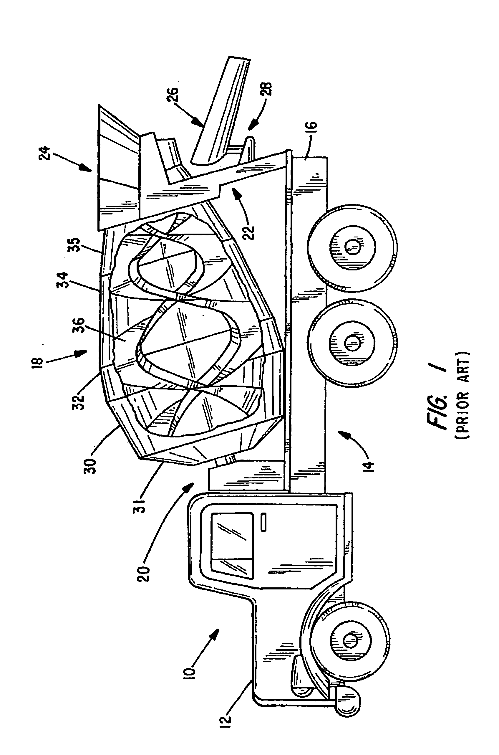
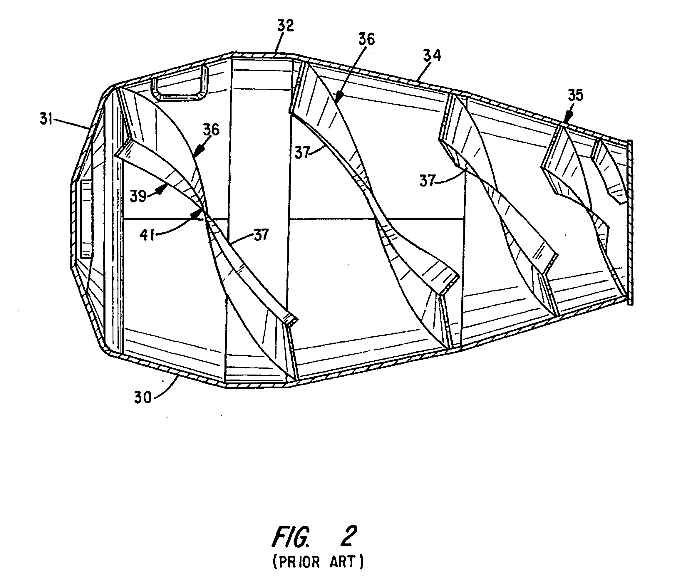
[0024]The pertinent parts of a typical conventional mobile system for mixing and dispensing concrete including the vehicle, mixing drum mounting arrangement and general dual fin system are illustrated in FIGS. 1 and 2 with the earlier description of related art.

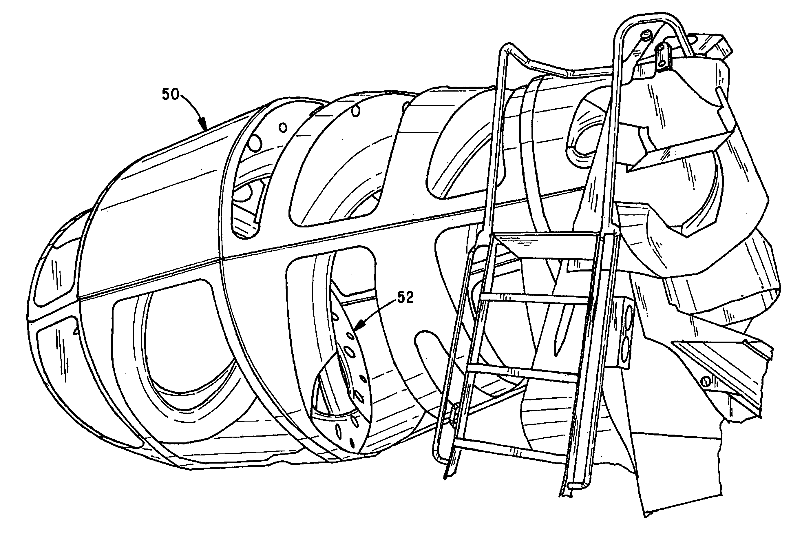
[0025]The concepts illustrated in FIGS. 3-6 of the drawings show an illustrative detailed embodiment of the present inventive concept.

[0026]FIG. 3 is a perspective view of a model of a mixing drum 50 with numerous parts cut away to expose an internal helical mixing fin system mounted therein, part ...


PUM

PropertyMeasurementUnit
diameteraaaaaaaaaa
diameteraaaaaaaaaa
diameteraaaaaaaaaa

Abstract

A dual spiral mixing fin assembly adapted to mix and guide material contained in a rotatable mixing drum of a type used in a transit concrete vehicle mixing system, the assembly includes dual spiral mixing fins extending transversely along a drum mixing space attachable to the inner surface of a mixing drum. The fins are provided with a plurality of spaced large openings for allowing mixed concrete and charged ingredient materials to migrate along a drum mixing space through the openings in both a forward and rearward direction. The fins also have a plurality of spaced small openings that accommodate the passage of cleanout materials along a drum mixing space. A plurality of strut members are attached to forward portions of the mixing fins and adapted to be fixed to the front interior surface of a mixing drum.

Description

CROSS-REFERENCED TO RELATED APPLICATIONS[0001]Not applicableSTATEMENT REGARDING FEDERALLY SPONSORED RESEARCH OR DEVELOPMENT[0002]Not applicableBACKGROUND OF THE INVENTION[0003]I. Field of the Invention The present invention relates to mobile systems carrying rotatable mixing drums for mixing charged ingredient materials and dispensing concrete. More specifically, this invention relates to a helical mixing fin assembly for mixing and moving materials within concrete mixing drums that involves a fin design structure that provides superior mixing of the charged ingredient materials within rotatable drum mixers.[0004]II. Related Art[0005]Concrete mixing trucks are widely used in the construction industry for preparing and transporting concrete mix to desired construction sites. Such trucks feature a large rotatable mixing drum which includes fins or agitators mounted inside for mixing and directing the movement of a concrete mixture therein. Such fins typically have a helical configurat...

Claims


Application Information

Patent Timeline
Patent Type & Authority Applications(United States)
IPC IPC(8): B28C5/18
CPCB28C5/1862B28C5/4268B01F29/63
Inventor MELDAHL, BRIAN R.ATTLESON, JAYMCNEILUS, GARWIN B.
Owner CON TECH MFG
Why Eureka
Try Eureka