Vehicular display device

a vehicular display and display device technology, applied in the direction of instruments, uv light devices, transportation and packaging, etc., can solve the problems of occupants' attention and appearance deterioration, and achieve the effect of wide display range, improved appearance of the display performed by the vehicular display device, and suitable mass production

Active Publication Date: 2016-08-04
DENSO CORP
View PDF12 Cites 15 Cited by
  • Summary
  • Abstract
  • Description
  • Claims
  • Application Information

AI Technical Summary

Benefits of technology

[0015]According to the fourth disclosure, since the plural monitors arranged side by side in the horizontal direction are disposed along the first display board even though the first display board is curved to have a curvature common to the second display board, a wide display range for the vehicle information displayed by the respective transmission display portions can be ensured. According to this structure, when the plural general-purpose monitors h

Problems solved by technology

As a result, the occupant is likely to pay attention to the boundary portions, i.e., discontinuous portions of the display of the vehicle information, between the

Method used


Image

  • Vehicular display device
  • Vehicular display device
  • Vehicular display device

Examples


first embodiment

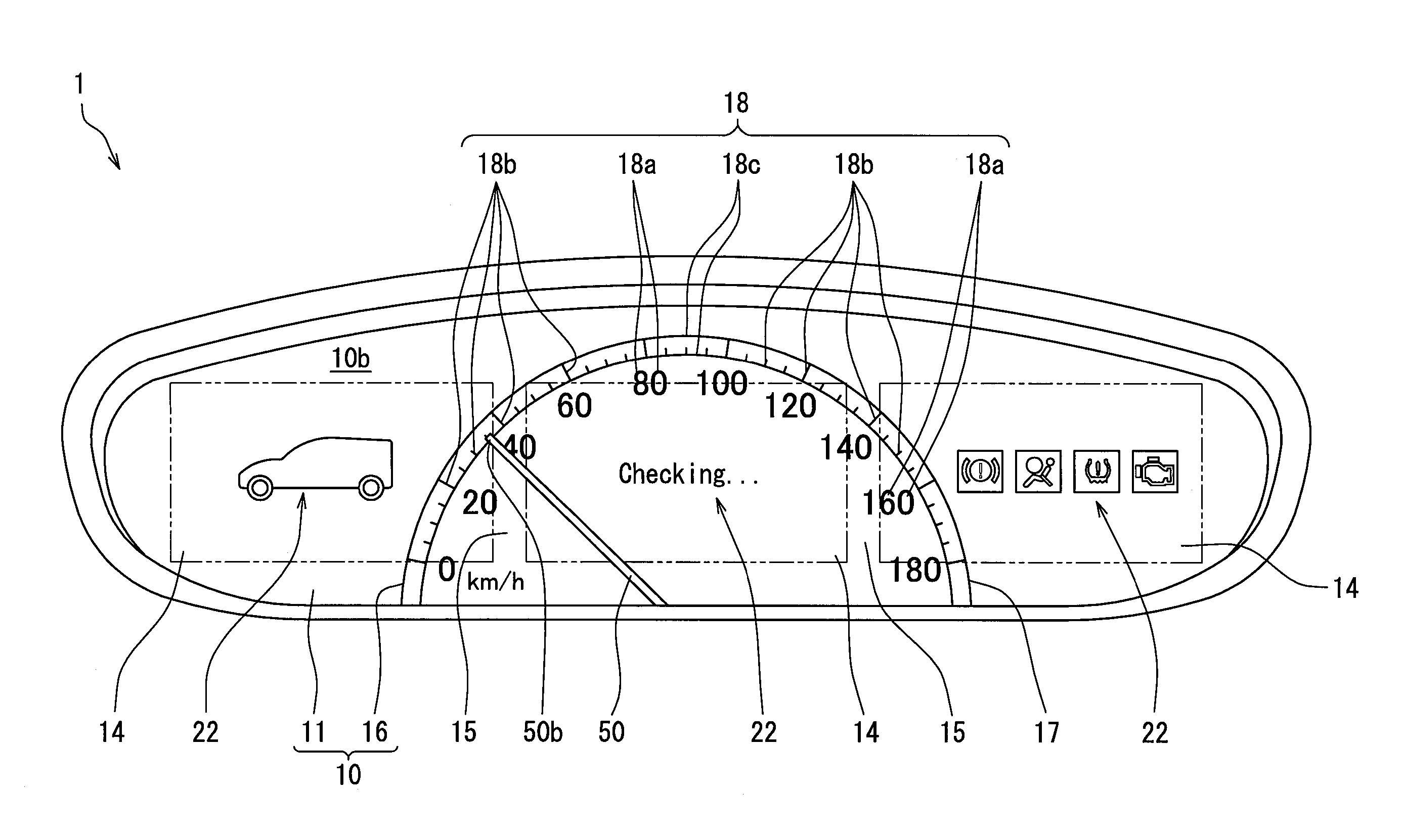
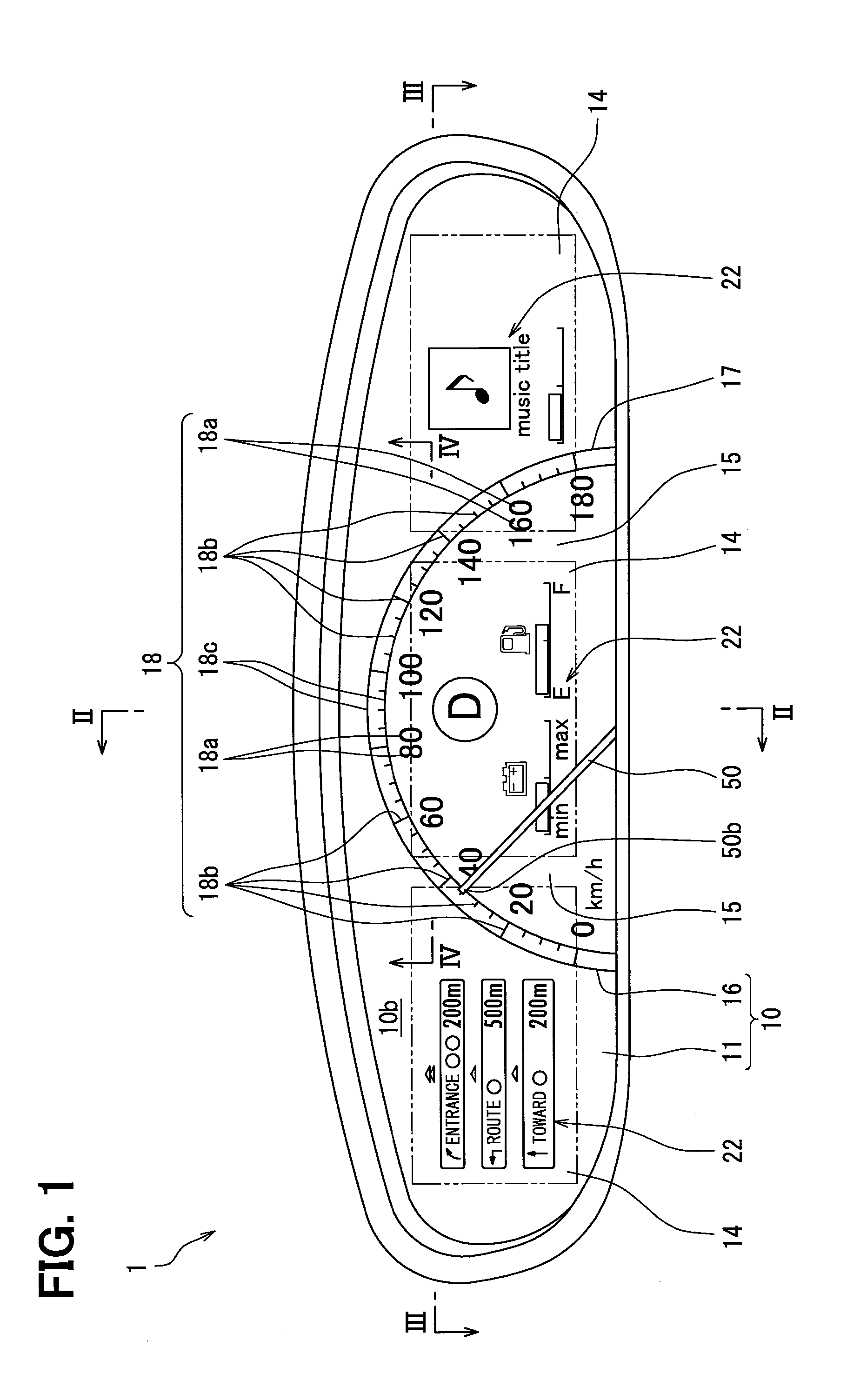
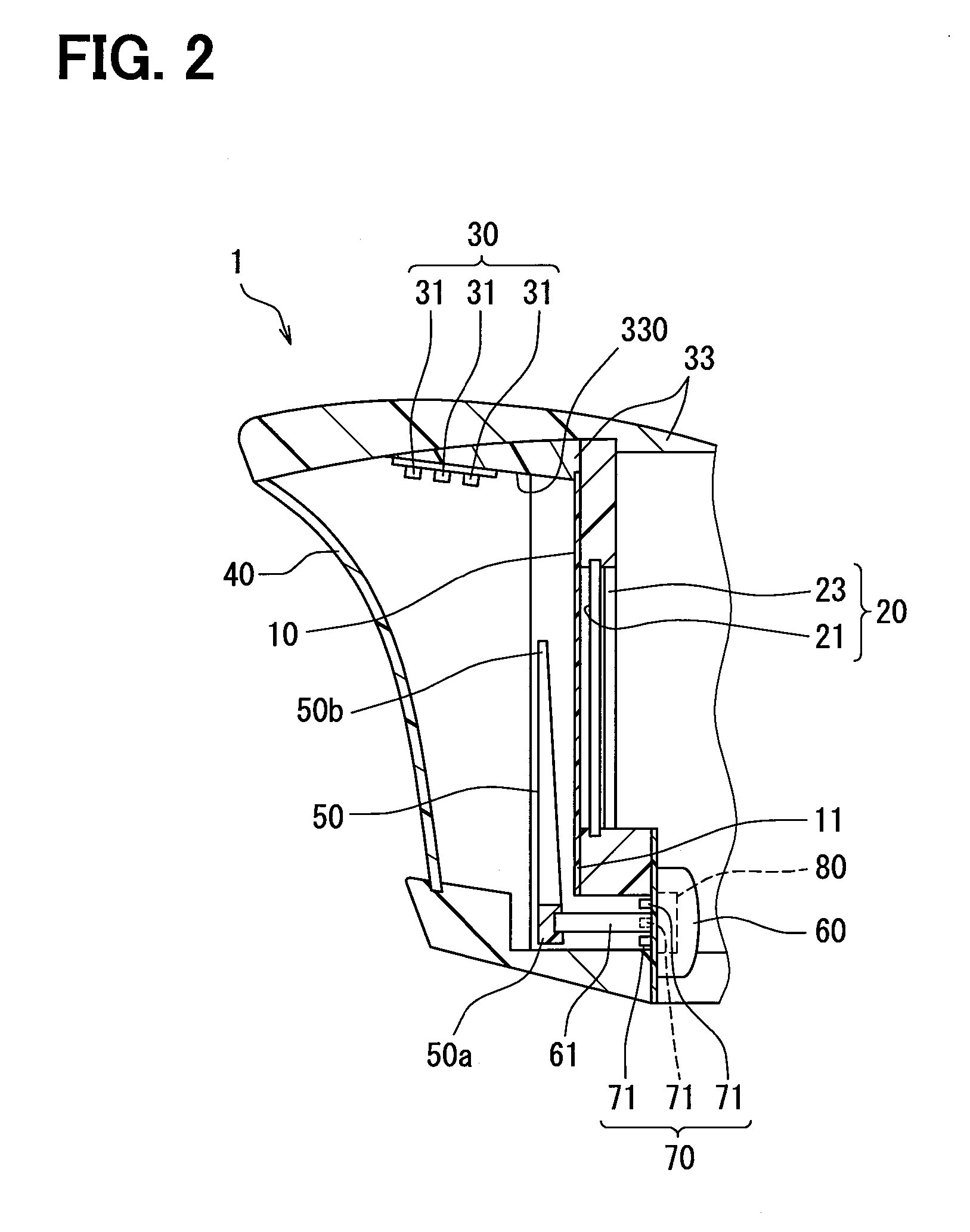
[0038]As shown in FIGS. 1 to 3, a vehicular display device 1 according to a first embodiment of this disclosure is a combination meter that displays information an occupant seated on a seat in a vehicle, and is installed on an instrument panel in the vehicle. Meanwhile, a “horizontal direction” and a “vertical direction” of the device 1 substantially correspond to a horizontal direction and a vertical direction of the vehicle in FIG. 1, respectively. A “front side” of the device 1 means a left side in FIG. 2 on which information is displayed to the occupant in the vehicle and a lower side in FIG. 3, that is, a side that is viewed by the occupant. A “rear side” of the device 1 means a right side in FIG. 2 that is opposite to the side on which information is displayed to the occupant in the vehicle and an upper side in FIG. 3.

[0039]The device 1 includes a display board 10, monitors 20, an index light source 30, a cover 40, a rotary pointer 50, a driving source 60, a pointer light sour...

second embodiment

[0063]As shown in FIGS. 9 and 10, a second embodiment of this disclosure is a modification of the first embodiment. In the second embodiment, the pointer light source 70 of FIG. 2 of the first embodiment is not provided as shown in FIG. 9 and a fluorescent layer, which emits light by using ultraviolet light, is formed on a rotary pointer 2050. Specifically, a fluorescent layer 2051 is formed on a front surface 2050c and both side surfaces 2050d of the rotary pointer 2050 as shown in FIG. 10. A translucent layer, which is made of an acrylic resin in which, for example, fluorite powder is melted and is colorless and transparent, is laminated on a translucent base material 2052 serving as a base material of the rotary pointer 2050 by printing or the like, so that the fluorescent layer 2051 is formed. The fluorescent layer 2051 is irradiated with ultraviolet light emitted from the respective light emitting elements 31 of the index light source 30, so that the entire rotary pointer 2050 ...

third embodiment

[0065]As shown in FIGS. 11 and 12, a third embodiment of this disclosure is a modification of the first embodiment. In an initial display state of the third embodiment, the respective light emitting elements 31 of the index light source 30 (not shown in FIGS. 11 and 12) are turned on by current flow control from the control circuit 80 as the rotary pointer 50 indicates irradiation target areas 3032 set as in the first embodiment. In other words, the respective light emitting elements 31 of the index light source 30 are turned off as a destination of the rotary pointer 50 deviates from the respective irradiation target areas 3032.

[0066]As described above, each of the plural light emitting elements 31 irradiating the respective irradiation target areas 3032, which are offset from each other, with ultraviolet light is turned on when the corresponding irradiation target area 3032 is indicated by the rotary pointer 50. As a result, the light emitting element irradiates the irradiation ta...


PUM


Abstract

A vehicular display device includes a plurality of monitors that include screens displaying vehicle information, a display board including a plurality transmission display portions each of which transmits and displays the screen of the respective monitors from a rear side and which are arranged side by side, a boundary portion that is positioned between the transmission display portions and an index display portion that forms an index row to display a vehicle state value, and an index light source that illuminates the index display portion. The index light source applies ultraviolet light for illuminating the index display portion to the index row from a front side of the display board, and the index row is formed in the display board in front of the transmission display portions over each of the transmission display portions interposing the boundary portion, and the index row is irradiated when receiving the ultraviolet light. Accordingly, the appearance of the display performed by the vehicular display device is improved.

Description

CROSS-REFERENCE TO RELATED APPLICATIONS[0001]The present application is based on Japanese patent applications No. 2013-192178 filed on Sep. 17, 2013 and No. 2014-168798 filed on Aug. 21, 2014 the contents of which are incorporated herein by reference.TECHNICAL FIELD[0002]The present disclosure relates to a vehicular display device that displays vehicle information.BACKGROUND ART[0003]A technique in which an index display portion is provided on a display board in a vehicular display device in addition to transmission display portions has been known in the past. The transmission display portions transmit and display monitor screens, which display vehicle information, from the rear side and the index display portion forms an index row with numerals, scales, and the like to display a vehicle state value.[0004]In a device disclosed in PTL 1 as a vehicular display device that employs the technique, plural monitor screens are individually displayed and transmitted by plural transmission di...

Claims


Application Information

Patent Timeline
IPC IPC(8): B60K35/00B60Q3/00B60Q3/04G01D11/28G01D11/24
CPCB60K35/00G01D11/28G01D11/24B60Q3/048B60Q3/008B60Q3/68B60Q3/18B60K37/02B60K2370/341B60K2370/343B60K2370/34B60K2370/154
Inventor TANE, SEIGOFUJITA, KATSUMI
Owner DENSO CORP
Why Eureka
Try Eureka