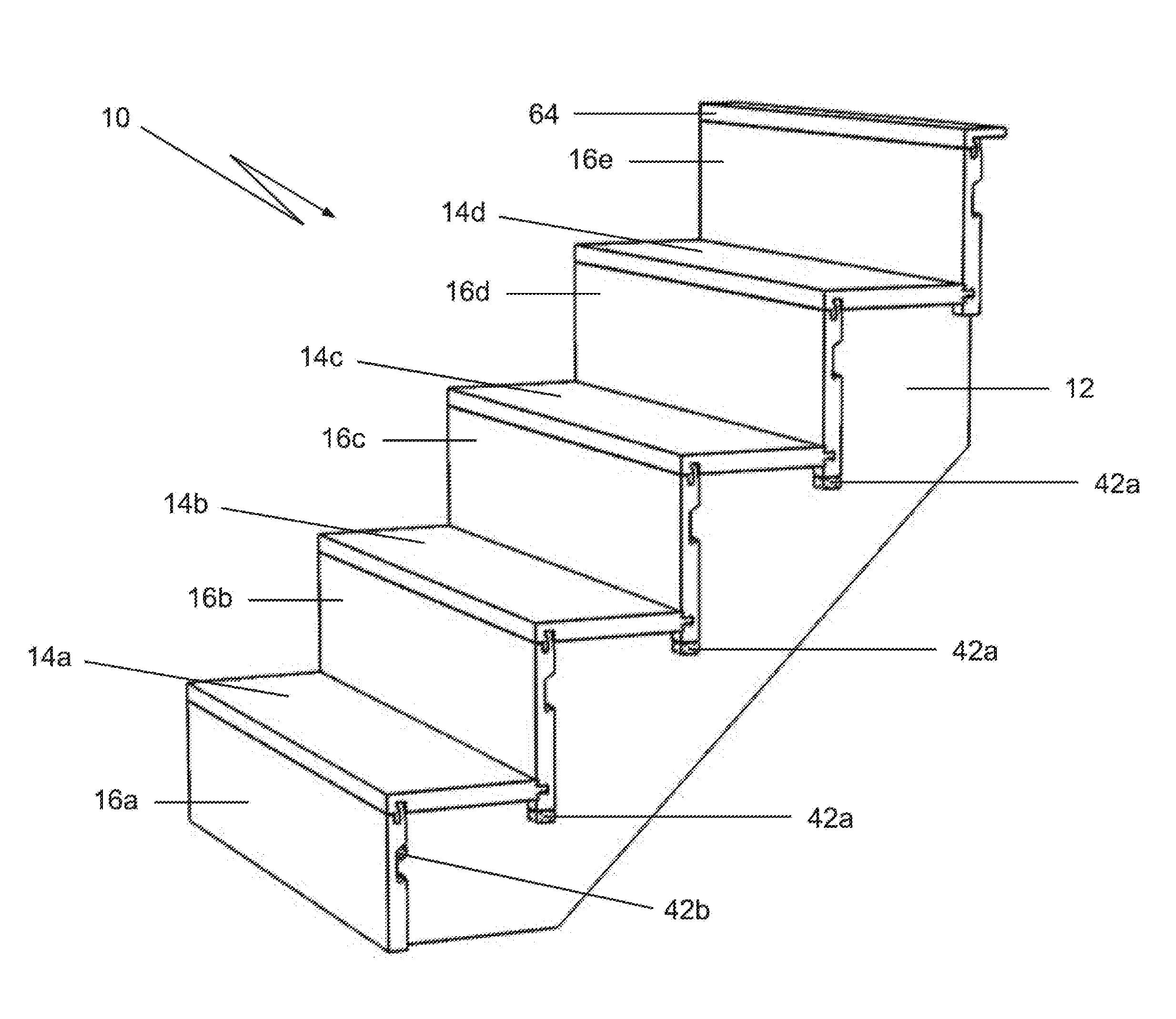
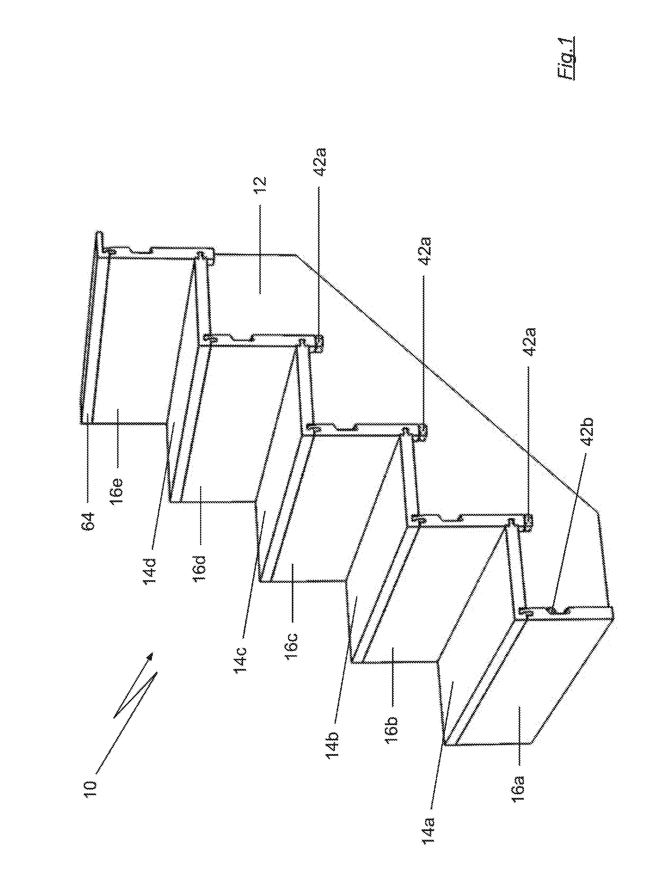
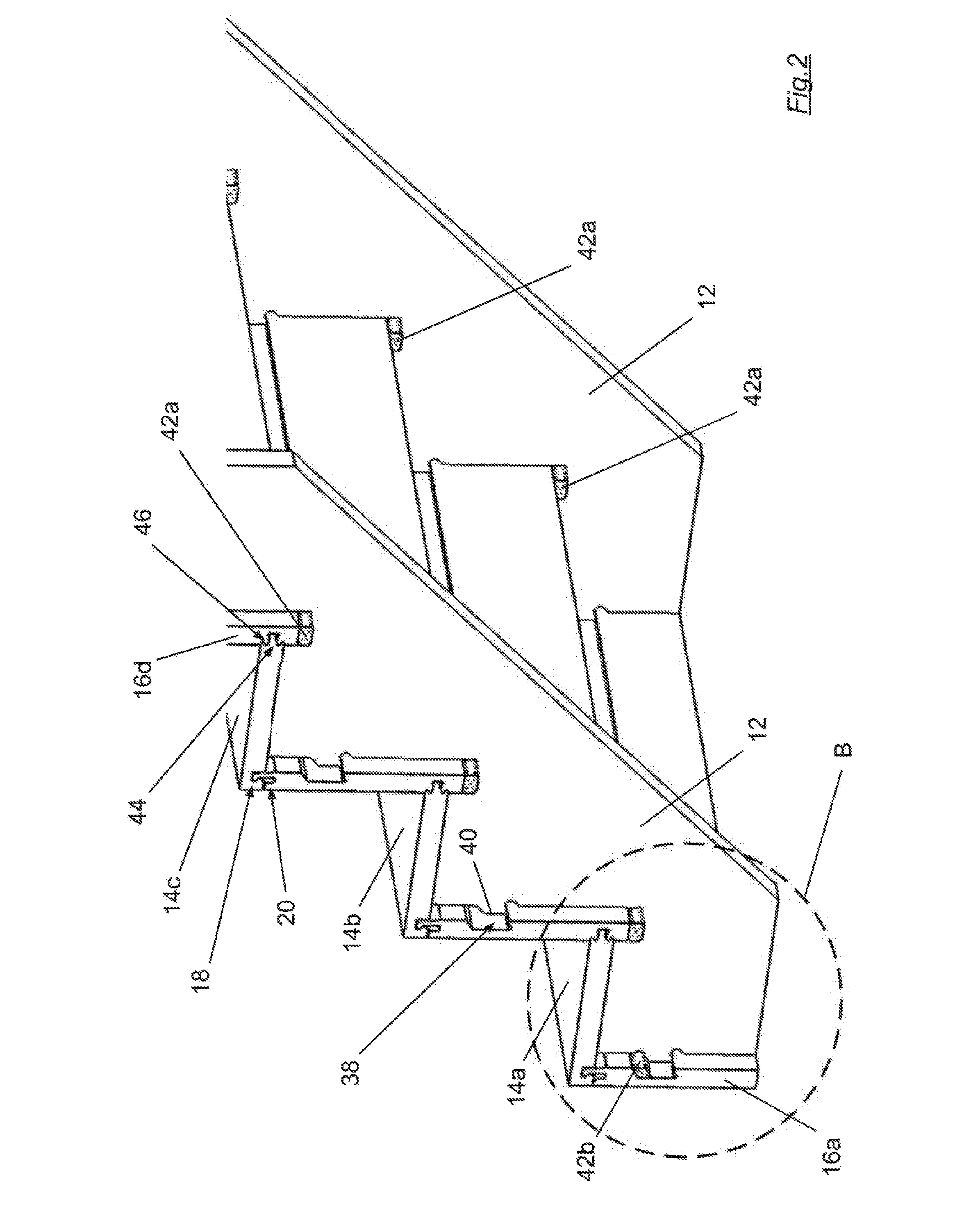
A stair case
a technology for stairs and stair cases, applied in the field of stairs, can solve the problems of time-consuming, labor-intensive stair case assembly, and inconvenience in work, and achieve the effect of reducing the number of stairs
- Summary
- Abstract
- Description
- Claims
- Application Information
AI Technical Summary
Benefits of technology
Problems solved by technology
Method used
Image
Examples
second embodiment
[0176]In this second embodiment, the third connecting elements each include a first transverse ridge 170 formed on the upper surface of the respective tread 114a to 114c, and a first transverse channel 172 formed on the under surface of the respective tread 114a to 114. The fourth connecting elements each include a second transverse ridge 174 formed in each of the tread supporting faces 132. When the third and fourth connecting elements are interconnected, the first transverse ridge 170 bears against one of the riser abutment faces 134. Further, the second transverse ridge 174 is located within the first transverse channel 172. When the third and fourth connecting elements are interconnected, the second transverse ridge 174 also bears against, the respective tread 114a to 114c. Thus, the first and second transverse ridges 170, 174 co-operate to inhibit translational movement of the respective treads 114a to 114c parallel to the respective tread supporting faces 132.
[0177]The stair c...
seventh embodiment
[0218]It will be appreciated that the segmented treads of the seventh embodiment readily accommodate the different rise and going in the risers and treads, respectively, of individual stair cases. To this end, the depth of the lateral portion 617 can be set to a desired dimension, whilst the tread toe portion 615b remains at a fixed depth. Similarly, the height of the uptight portion 619 can be set to a desired dimension, whilst the riser 16 remain at a fixed height. As will be further appreciated, the segmented treads facilitate standardization of the tread toe segments and risers within stair cases.
[0219]In one example shown in FIG. 47, the tread nose segment 615a′ has a short lateral portion 617 and a short upright portion 619′. In another example shown in FIG. 48, the tread nose segment 615a″ has a short lateral portion 617″ and a long upright portion 619″. In yet another example shown in FIG. 49, the tread nose segment 615a′″ has a long lateral portion 617′″ and a short upright...
eighth embodiment
[0221]FIG. 51 is a side view of a tread nose segment 715a, and a partial view of a tread toe segment 715b, a riser 716 and a stringer 712 according to an eighth embodiment, these components being similar to those shown in FIG. 46. Accordingly, in FIG. 51, the components that are substantially similar to those shown in FIG. 46 have the same reference numeral with the prefix “6” replaced with the prefix “7”.
[0222]The tread nose segment 715a further includes an overlapping portion 725 that extends rearwardly from the lateral portion 717, and over a front portion of the tread toe segment 715b. The overlapping portion 725 has a barbed lip 727 that engages in a complementary shaped groove 729 formed in the upper surface of the tread toe segment 715b. The overlapping portion 725 provide protection to the interface between the nose and toe segments 715a, 715b, as may be required in stair cases that are subjected to high foot traffic, and / or that require an anti-slip feature at the nose of e...
PUM
 Abstract
Description
Claims
Application Information
 - R&D
- Intellectual Property
- Life Sciences
- Materials
- Tech Scout
- Unparalleled Data Quality
- Higher Quality Content
- 60% Fewer Hallucinations
Browse by: Latest US Patents, China's latest patents, Technical Efficacy Thesaurus, Application Domain, Technology Topic, Popular Technical Reports.
© 2025 PatSnap. All rights reserved.Legal|Privacy policy|Modern Slavery Act Transparency Statement|Sitemap|About US| Contact US: help@patsnap.com


