Devices and methods to facilitate eye positioning and eye drop installation

a technology for eye drops and devices, applied in the field of eye drops, can solve the problems of eye drops being misapplied, eye drops being difficult to place, eye drops being smacked, etc., and achieve the effect of efficient medication application, assembled and disassembled

Inactive Publication Date: 2016-08-11
MICHALOS PETER
View PDF14 Cites 8 Cited by
  • Summary
  • Abstract
  • Description
  • Claims
  • Application Information

AI Technical Summary

Benefits of technology

[0006]It is an object of the present invention to provide an eye drop applicator to a frame assembly having opaque eye plates with a liquid aperture and an optical aperture in each eye plate that allows efficient application of medications, and that is configured to be assembled and disassembled without using a tool.
[0008]A left temple includes a first temple-engagement-structure configured to be removably engagable with the first left front-engagement-structure and a second temple-engagement-structure configured to be removably engagable with the second left front-engagement-structure; and a right temple including a first temple-engagement-structure and a second temple-engagement-structure, the right temple being subject to deformation force such that a distance E between the first and second temple-engagement-structures has a first inequality relation to a distance S between the first and second right front-engagement-structures, the right temple being resilient such that, after deformation ceases, the distance E has a second inequality relation to the distance S, the second inequality relation being an inverse of the first inequality relation, thereby enabling the right temple to be removably attachable to the frame front, without using a tool.
[0009]According to another aspect of the present invention, a frame assembly for wearing on the head of a person comprises a frame front, the frame front including a left eye plate having a first opaque major surface defining a first optical aperture and a first liquid aperture; a right eye plate, coupled to the left eye plate. The right eye plate has a second opaque major surface defining a second optical aperture and a second liquid aperture, the first optical aperture and the first liquid aperture defining a line transverse to a line defined by the first and second optical apertures, and the second optical aperture and the second liquid aperture defining a line transverse to the line defined by the first and second optical apertures. The frame front includes a first left surface defining a first left hole; a second left surface defining a second left hole; a first right surface defining a first right hole; a second right surface defining a second right hole. A left temple includes a first post configured to be removably engagable with the first left hole and a second post configured to be removably engagable with the second left hole; and a right temple includes a first post defining a first extremity and a second post defining a second extremity, the right temple being subject to deformation force such that a distance E between the first and second extremities has a first inequality relation to a distance S between the first and second right surfaces, the right temple being resilient such that, after deformation ceases, the distance E has a second inequality relation to the distance S, the second inequality relation being an inverse of the first inequality relation, thereby enabling the right temple to be removably attachable to the frame front, without using a tool.

Problems solved by technology

Placement of eye drops can be challenging, especially for people having certain conditions such as Arthritis or Parkinson's disease.
Some conventional methods of applying eye drops can result in misapplication of the eye drops and the risk of poking the eye and scratching the cornea.

Method used


Image

  • Devices and methods to facilitate eye positioning and eye drop installation
  • Devices and methods to facilitate eye positioning and eye drop installation
  • Devices and methods to facilitate eye positioning and eye drop installation

Examples


Embodiment Construction

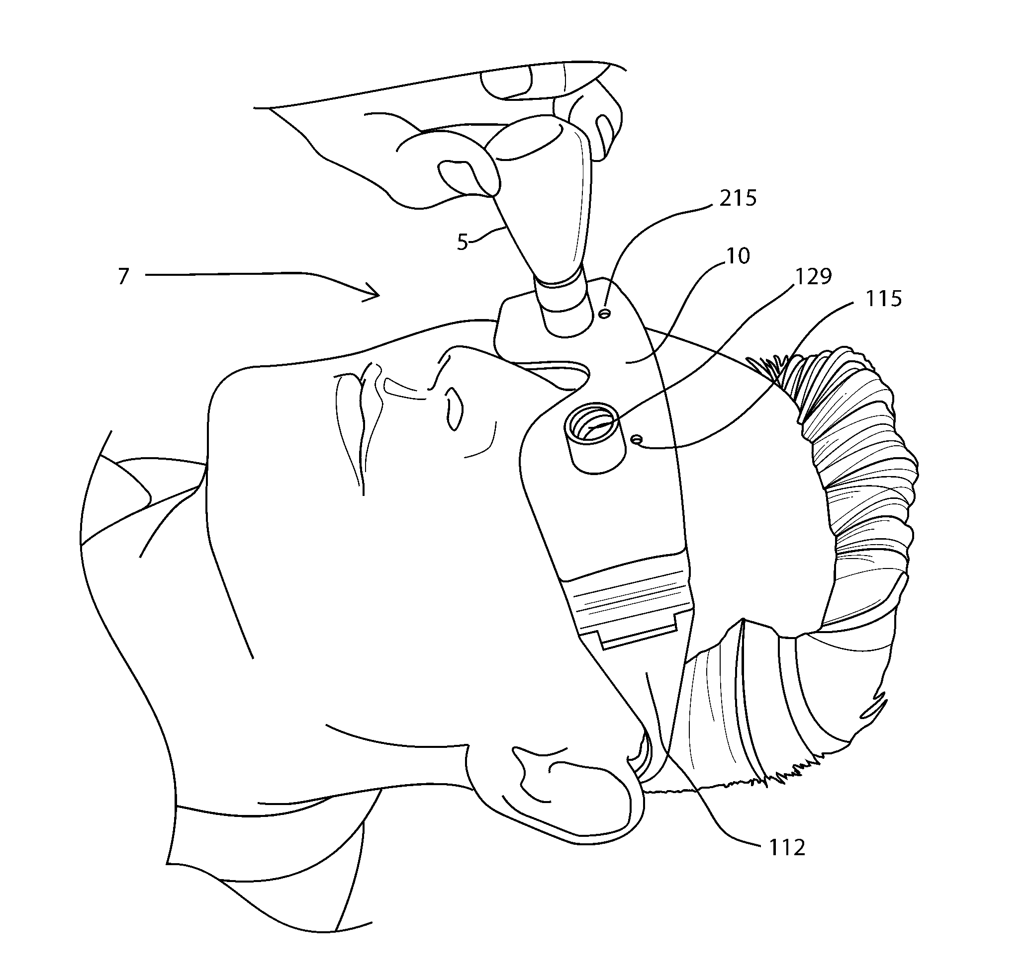
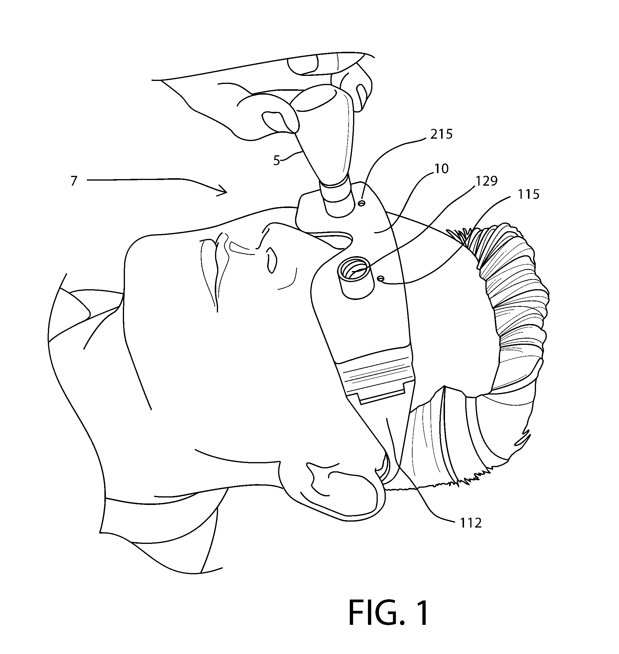
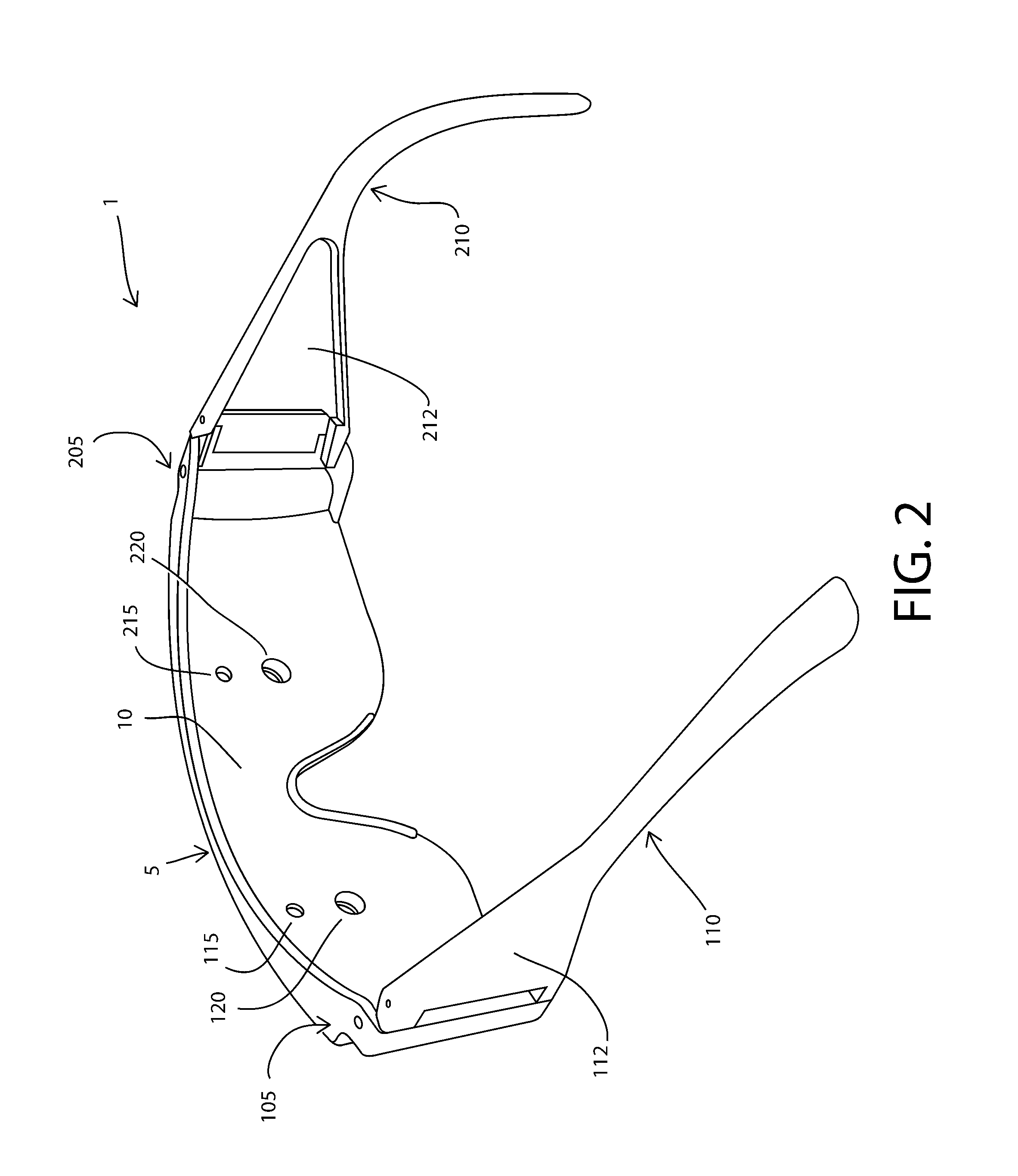
[0022]FIG. 1 shows a front perspective view of an exemplary frame assembly 1 according to a preferred embodiment of the present invention, and FIG. 2 is a back perspective view of frame assembly 1. Frame assembly 1 includes a front part 5 having an opaque major surface 10. A disassemblable hinge 105 couples a left temple 110 to the front part 5. The left temple 110 extends away from the opaque surface 10 in a direction transverse to the opaque surface 10, when the hinge 205 is in an open position.

[0023]A disassemblable hinge 205 couples a right temple 210 to the front part 5. Right temple 210 extends away from the opaque surface 10 in a direction transverse to the opaque surface 10, when the hinge 205 is in an open position.

[0024]The combination of left temple 110 and right temple 210 acts to secure eye front part 5 to the head of person 7.

[0025]The opaque surface 10 defines an optical aperture 115 and a liquid aperture 120. The liquid aperture 120 has a diameter of 5 mm, which is s...


PUM


Abstract

A frame assembly, for wearing on the head of a person, includes left and right eye plates, each having an optical aperture and a liquid aperture. A temple includes a first post defining a first extremity and a second post defining a second extremity. The temple is subject to compression force such that a distance E between the first and second extremities is less that a distance S between holes on the frame front. The temple is resilient such that, after compression ceases, the distance E is greater than the distance S, thereby enabling the temple to be removably attachable to the frame front, without using a tool.

Description

[0001]This Application claims the benefit of U.S. Provisional Patent Application 62 / 072,434 filed 30 Oct. 2014 of PETER MICHALOS for EYEDROP DELIVERY SYSTEM, the contents of which are herein incorporated by reference.BACKGROUND OF THE INVENTION[0002]1. Field of the Invention[0003]This invention relates generally to applying eye drops to human eyes and, more particularly, to applicators that facilitate application of eye drops.[0004]2. Description of Related Art[0005]Placement of eye drops can be challenging, especially for people having certain conditions such as Arthritis or Parkinson's disease. Some conventional methods of applying eye drops can result in misapplication of the eye drops and the risk of poking the eye and scratching the cornea.SUMMARY OF THE INVENTION[0006]It is an object of the present invention to provide an eye drop applicator to a frame assembly having opaque eye plates with a liquid aperture and an optical aperture in each eye plate that allows efficient appli...

Claims


Application Information

Patent Timeline
Patent Type & Authority Applications(United States)
IPC IPC(8): A61F9/00G02C5/00G02C5/14G02C11/00G02C5/16
CPCA61F9/0026G02C5/2209G02C5/146G02C11/00
Inventor MICHALOS, PETER
Owner MICHALOS PETER
Why Eureka
Try Eureka