
"Vented Draining Slack Adjuster End Cap"

a slack adjuster and end cap technology, applied in the direction of slack adjusters, rail brake actuation, rail braking systems, etc., can solve the problems of affecting the performance of springs and washing out operating grease, faulty operation of slack adjusters, and affecting the operation of springs, etc., to reduce the effect of reducing the exposure of the critical operating area

Active Publication Date: 2016-08-11
WESTINGHOUSE AIR BRAKE TECH CORP
View PDF4 Cites 6 Cited by
  • Summary
  • Abstract
  • Description
  • Claims
  • Application Information

AI Technical Summary

Benefits of technology

The present patent provides a drainage system for a slack adjuster used in a railway brake rigging system. The system includes an end cap with at least one opening that allows fluid and contaminants to drain out of the slack adjuster and reduce exposure to components within the main spring housing. The end cap can have multiple openings and longitudinally extending apertures in fluid communication with the radially extending openings and the interior of the main spring housing. The system also includes seals and sealing systems along the body of the slack adjuster to seal the critical operating area against fluid and contaminants. The technical effects of the drainage system include reducing exposure of components and protecting the critical operating area from fluid and contaminants.

Problems solved by technology

This water and other contaminants from the environment can accumulate and become trapped within the slack adjuster in the main spring housing or even in the critical operating area and near critical components of the slack adjuster, which can compromise the functioning of the slack adjuster.
However, when a slack adjuster is exposed to large amounts of water, this wiper seal can fail to block all of the water from entering into the main spring housing, affecting spring performance and washing out operating grease and, subsequently, entering into the critical operating area of the slack adjuster.
Thus, in these instances, water and contaminants may enter into the main spring housing and then into the critical operating area, deleteriously effecting the components located therein, resulting in faulty operation of the slack adjuster.

Method used


Image

  • "Vented Draining Slack Adjuster End Cap"
  • "Vented Draining Slack Adjuster End Cap"
  • "Vented Draining Slack Adjuster End Cap"

Examples


Embodiment Construction

[0049]For purposes of the description hereinafter, the terms “upper”, “lower”, “right”, “left”, “vertical”, “horizontal”, “top”, “bottom”, “lateral”, “longitudinal”, and derivatives thereof, shall relate to the disclosure as it is oriented in the drawing figures. However, it is to be understood that the disclosure may assume various alternative variations, except where expressly specified to the contrary. It is also to be understood that the specific devices illustrated in the attached drawings, and described in the following specification, are simply exemplary embodiments of the disclosure. Hence, specific dimensions and other physical characteristics related to the embodiments disclosed herein are not to be considered as limiting.

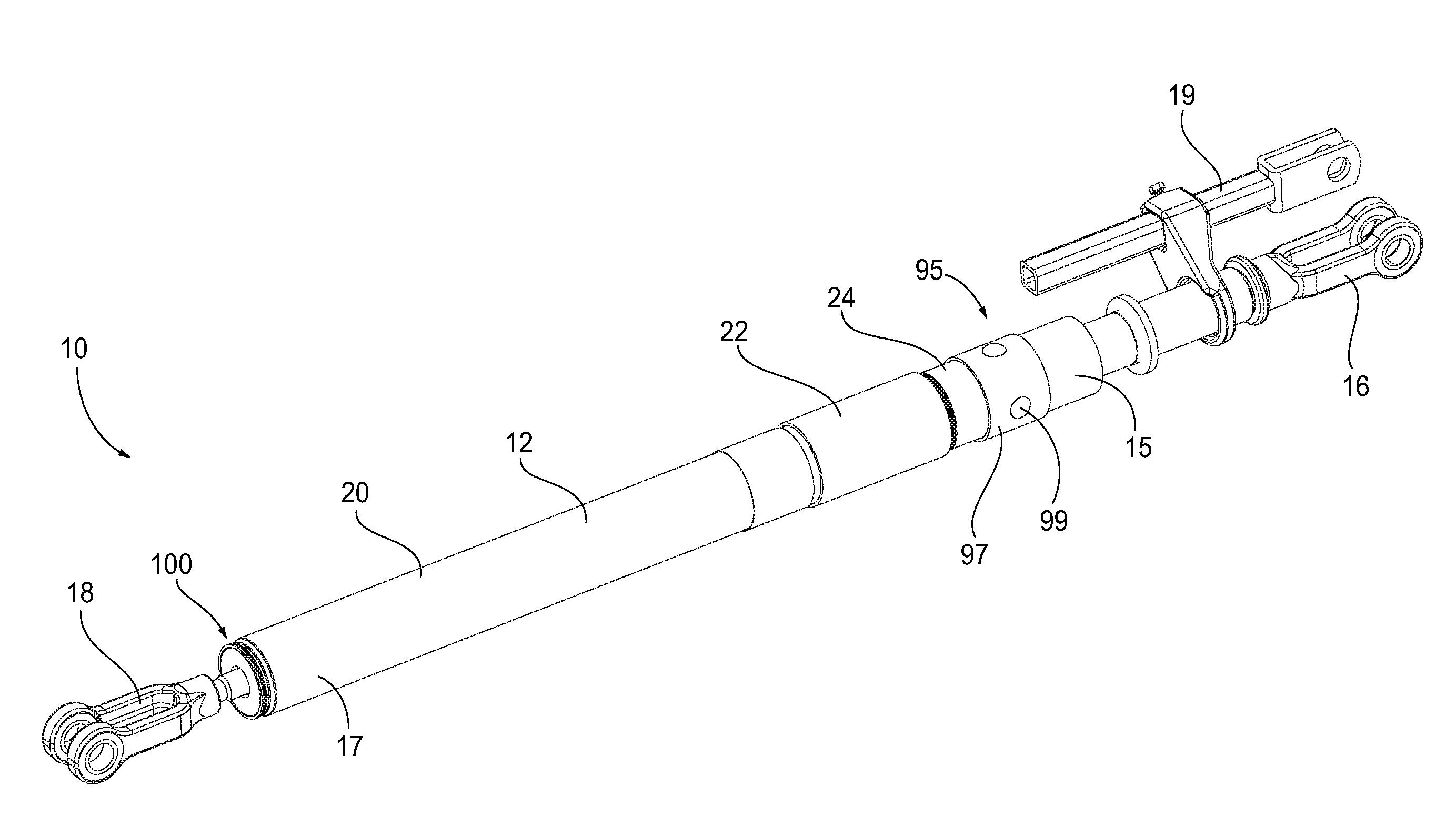
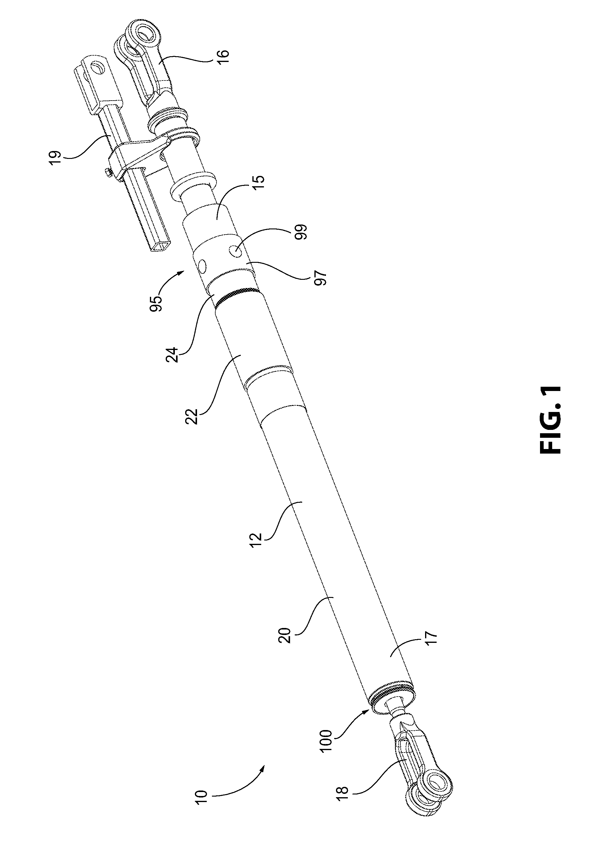
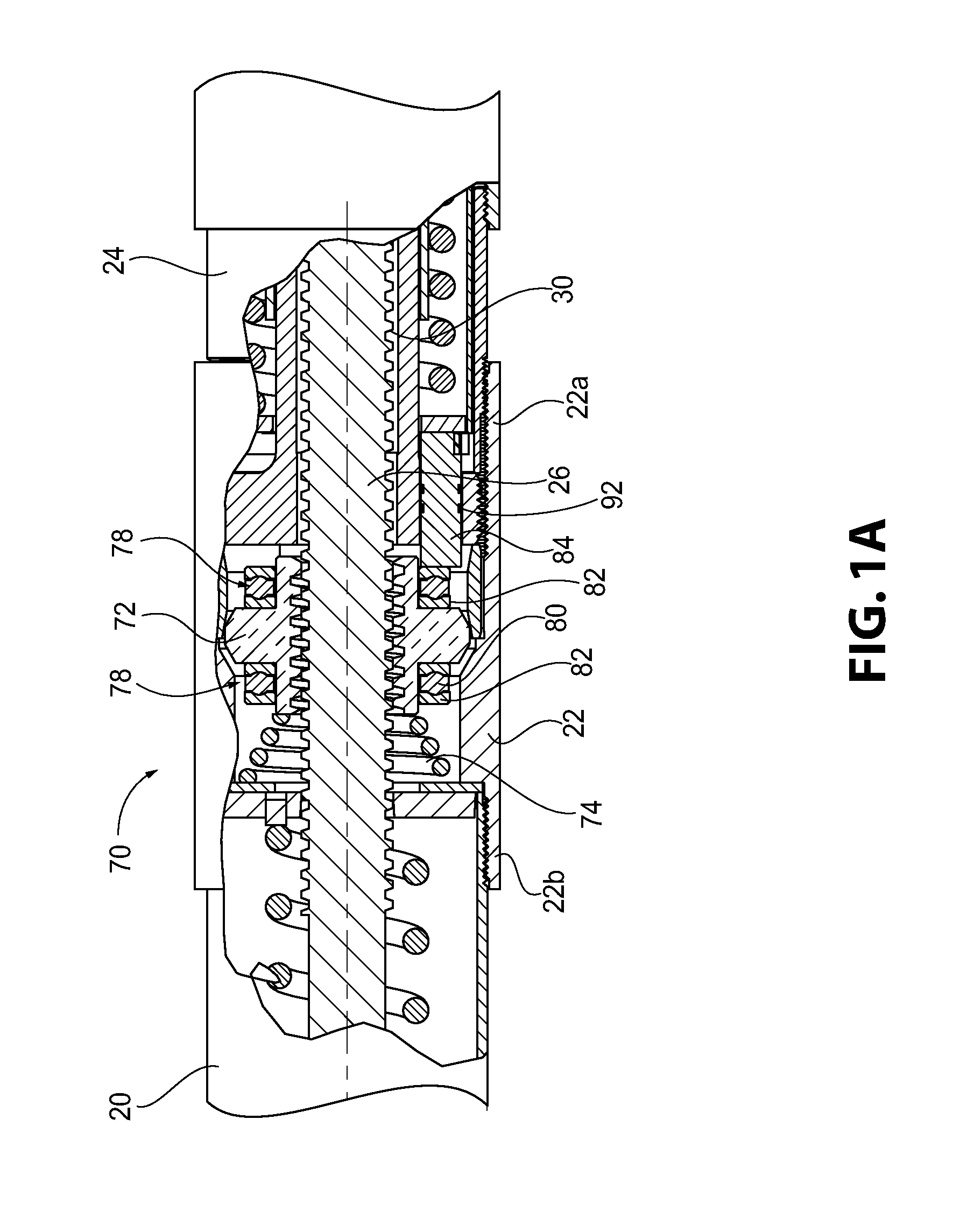
[0050]Reference is now made to FIGS. 1-3 which show a double acting slack adjuster, generally indicated as 10, for use in a railway vehicle brake linkage, not shown, to automatically adjust the slack within the brake linkage caused by wear induced in the ...


PUM


Abstract

A vented cap for a main spring housing of a slack adjuster including an inner portion having an inner seal surface configured for cooperating with an elongated rod member and an outer seal surface configured for cooperating with a sidewall located at an end portion of the main spring housing. The vented end cap includes at least one opening configured to allow fluid and / or contaminants trapped within the slack adjuster and / or the end cap to drain therethrough. Various seals and / or drainage openings can also be provided along the slack adjuster to prevent the entrance of and / or allow for drainage of fluid / contaminants from the slack adjuster. A method for preventing the accumulation of fluid and / or contaminants within a slack adjuster and for protecting a critical operating area of the slack adjuster is also provided.

Description

CROSS REFERENCE TO RELATED APPLICATIONS[0001]The present application is entitled to and claims priority of U.S. Provisional Patent Application No. 62 / 112,996, filed on Feb. 6, 2015, entitled “Vented Draining Slack Adjuster End Cap” the disclosure of which is incorporated herein by reference in its entirety.BACKGROUND OF THE INVENTION[0002]1. Field of the Invention[0003]The present disclosure is directed to a slack adjuster which automatically adjusts the slack in the brake rigging of a railway vehicle, and further, particularly, to a slack adjuster including a main spring housing end cap that also functions as an exit location for fluids and other contaminants that may enter the main spring housing of the slack adjuster, while preventing fluid and other contaminants from entering into the slack adjuster.[0004]2. Description of Related Art[0005]Slack adjuster assemblies have been employed in brake riggings to compensate for slack caused by wear induced in the brake pads, wheels, and ...

Claims


Application Information

Patent Timeline
IPC IPC(8): B61H15/00
CPCB61H15/0057B61H13/34F16D65/66B61H15/00
Inventor WHALEN, SHAUN T.GREGAR, PETER PAULNATSCHKE, SCOTT LEE
Owner WESTINGHOUSE AIR BRAKE TECH CORP
Learn More