
Skiing apparatus

Active Publication Date: 2016-08-11
BOOMERANG HLDG L L C
View PDF0 Cites 9 Cited by
  • Summary
  • Abstract
  • Description
  • Claims
  • Application Information

AI Technical Summary

Benefits of technology

[0007]With the above in mind, embodiments of the present invention are related to a skiing apparatus which may provide a greater ability of users to ski and also provide enhanced suspension dampening features. Embodiments of the present invention may also advantageously allow for a modular design so that skis may be easily changed. The skiing apparatus according to embodiments of the present invention may also advantageously allow for efficient transportation for users, as well as ease of manufacture of the skiing apparatus.
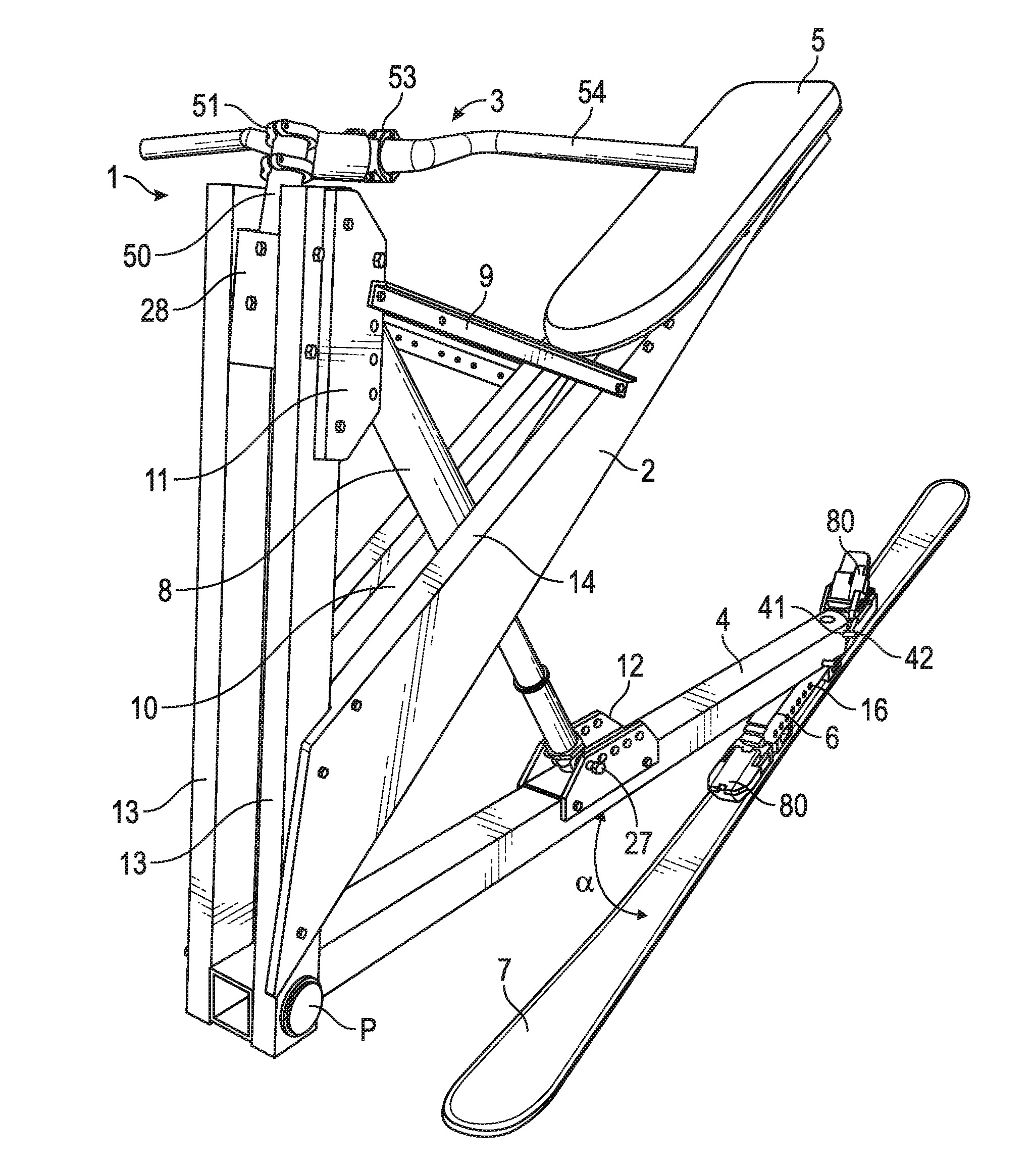
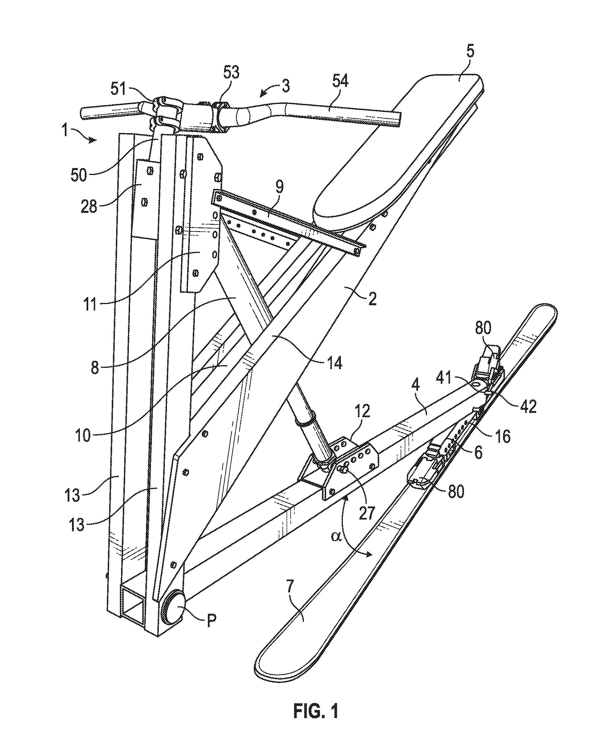
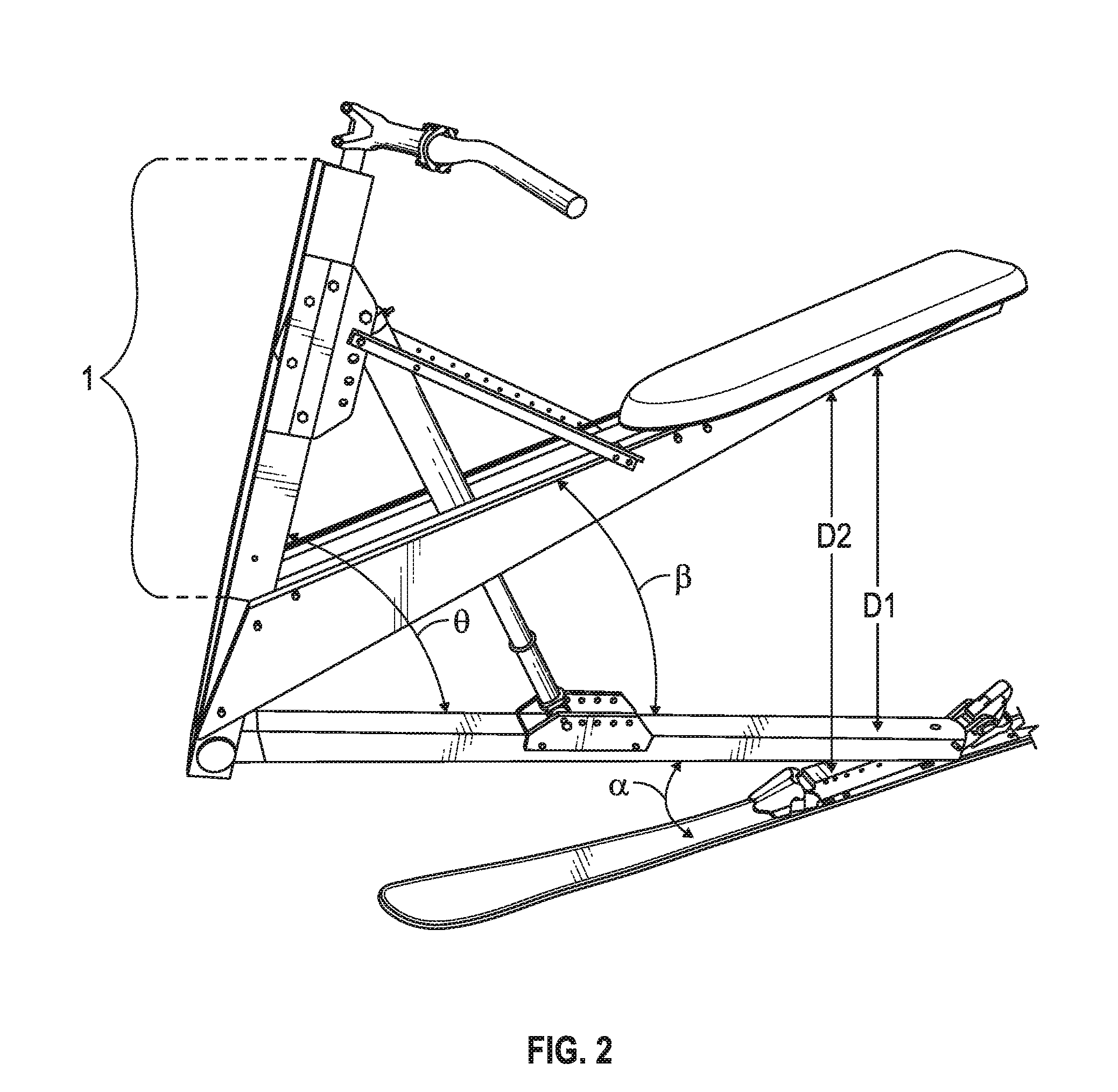
[0027]The skiing apparatus may include an upper frame member, a lower seat member, a handle member, a lower frame member, a ski attachment member, an upper shock absorbing connector member, a lower shock absorbing connector member, and a shock absorbing member. The lower seat member may include a first top member, a first front member, a first bottom member, a first brace, a second top member, a second front member, a second bottom member, and a second brace. The first top member may have a first end and a second end. The first front member may have a first end and a second end. The first end of the first front member may secure to the first end of the first top member at a first vertex.

Problems solved by technology

Traditionally, snow skiing apparatuses have been complicated and thus expensive to build and maintain.
Additionally, the small range of movement between the seat and the ski may render the skiing apparatus unsuitable for certain uses and terrains.
If the seat is movable in relationship to one or more of the skis, the movement range during operation is normally quite limited and cannot absorb large impacts and changes in terrain.
This severely limits the terrain on which the ski bikes may comfortably operate and the ability of the ski bike to absorb ground impacts.
These designs also tend to be quite complex and expensive to manufacture.

Method used


Image

  • Skiing apparatus
  • Skiing apparatus
  • Skiing apparatus

Examples


Embodiment Construction

[0047]The present invention will now be described more fully hereinafter with reference to the accompanying drawings, in which preferred embodiments of the invention are shown. This invention may, however, be embodied in many different forms and should not be construed as limited to the embodiments set forth herein. Rather, these embodiments are provided so that this disclosure will be thorough and complete, and will fully convey the scope of the invention to those skilled in the art. Those of ordinary skill in the art realize that the following descriptions of the embodiments of the present invention are illustrative and are not intended to be limiting in any way. Other embodiments of the present invention will readily suggest themselves to such skilled persons having the benefit of this disclosure. Like numbers refer to like elements throughout. Prime notation is used to identify similar elements in different embodiments.

[0048]Although the following detailed description contains m...


PUM


Abstract

A skiing apparatus including an upper frame member, a lower seat member, a handle member, a lower frame, a ski attachment member, an upper shock absorbing connector member, and a lower shock absorbing connector member. The lower seat member has a medial portion connected to the upper frame member. The handle member is connected to the upper frame member in fixed relation to the lower seat member. The lower frame member is connected to the lower seat member. The ski attachment member is connected to the lower frame member and adapted to be detachably connected to a ski. The upper shock absorbing connector member is connected to the lower seat member. The lower shock absorbing connector member is connected to the lower frame member.

Description

RELATED APPLICATIONS[0001]This application is a continuation-in-part and claims the benefit under 35 U.S.C. §120 of U.S. application Ser. No. 14 / 523,416, the entire contents of which are incorporated herein by reference except to the extent that the disclosure therein is inconsistent with the content herein.FIELD OF THE INVENTION[0002]The present invention relates to a snow skiing apparatus. In particular, the present invention relates to a snow skiing apparatus that a user may ride on in the manner of a skiing bicycle.BACKGROUND[0003]Traditionally, snow skiing apparatuses have been complicated and thus expensive to build and maintain. Additionally, the small range of movement between the seat and the ski may render the skiing apparatus unsuitable for certain uses and terrains.[0004]Traditional ski bikes normally have a seat of some kind on which the user sits and include two skis, a front ski and a back ski. The front ski is normally rotatable through the use of a rotatable handle ...

Claims


Application Information

Patent Timeline
IPC IPC(8): B62B17/06B62B13/06B62B17/02B62B13/04
CPCB62B13/005B62B17/062B62B13/043B62B17/063B62B17/02B62B17/061B62B13/06A63C2203/065A63C5/075
Inventor RAPP, JEFF
Owner BOOMERANG HLDG L L C
Learn More