
Method of removing an elongated structure implanted in biological tissue

Active Publication Date: 2008-04-15
COOK MEDICAL TECH LLC
View PDF15 Cites 63 Cited by
  • Summary
  • Abstract
  • Description
  • Claims
  • Application Information

AI Technical Summary

Benefits of technology

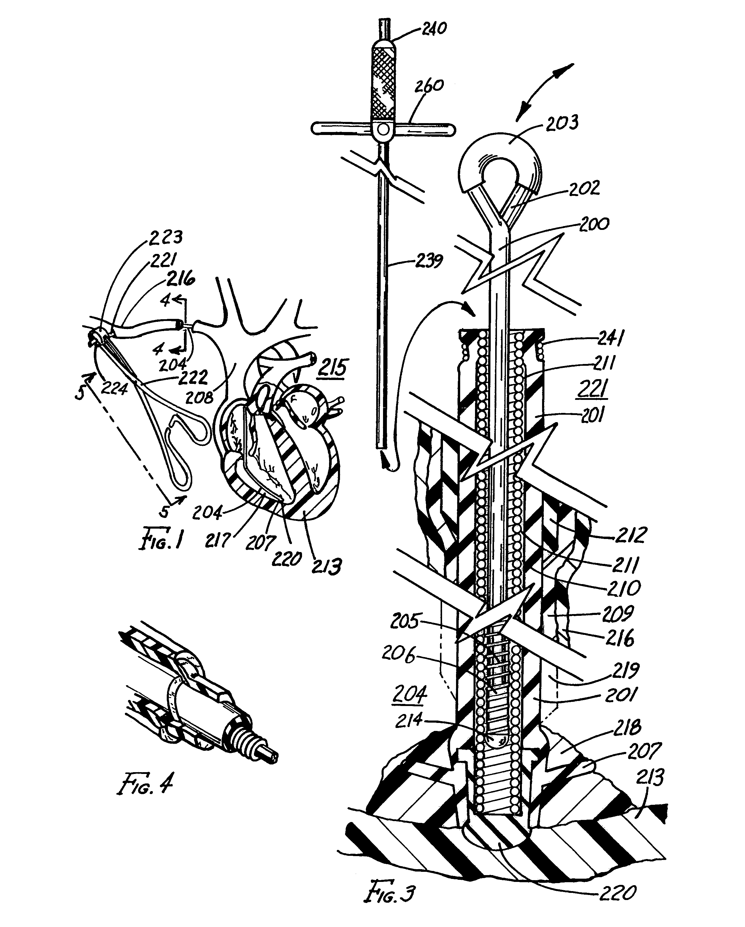
[0014]In another aspect, the expandable means includes a slotted sleeve positioned between the distal ends of the outer tube and the actuator rod. The ends of the tube and rod engage the slotted sleeve when expanding the slotted sleeve to an expanded position, which hooks into the coiled structure for securing the actuator rod to the coiled structure. The distal ends of the rod and the outer tube are beveled for easing expansion of the slotted sleeve when the actuator rod is withdrawn from the outer tube.
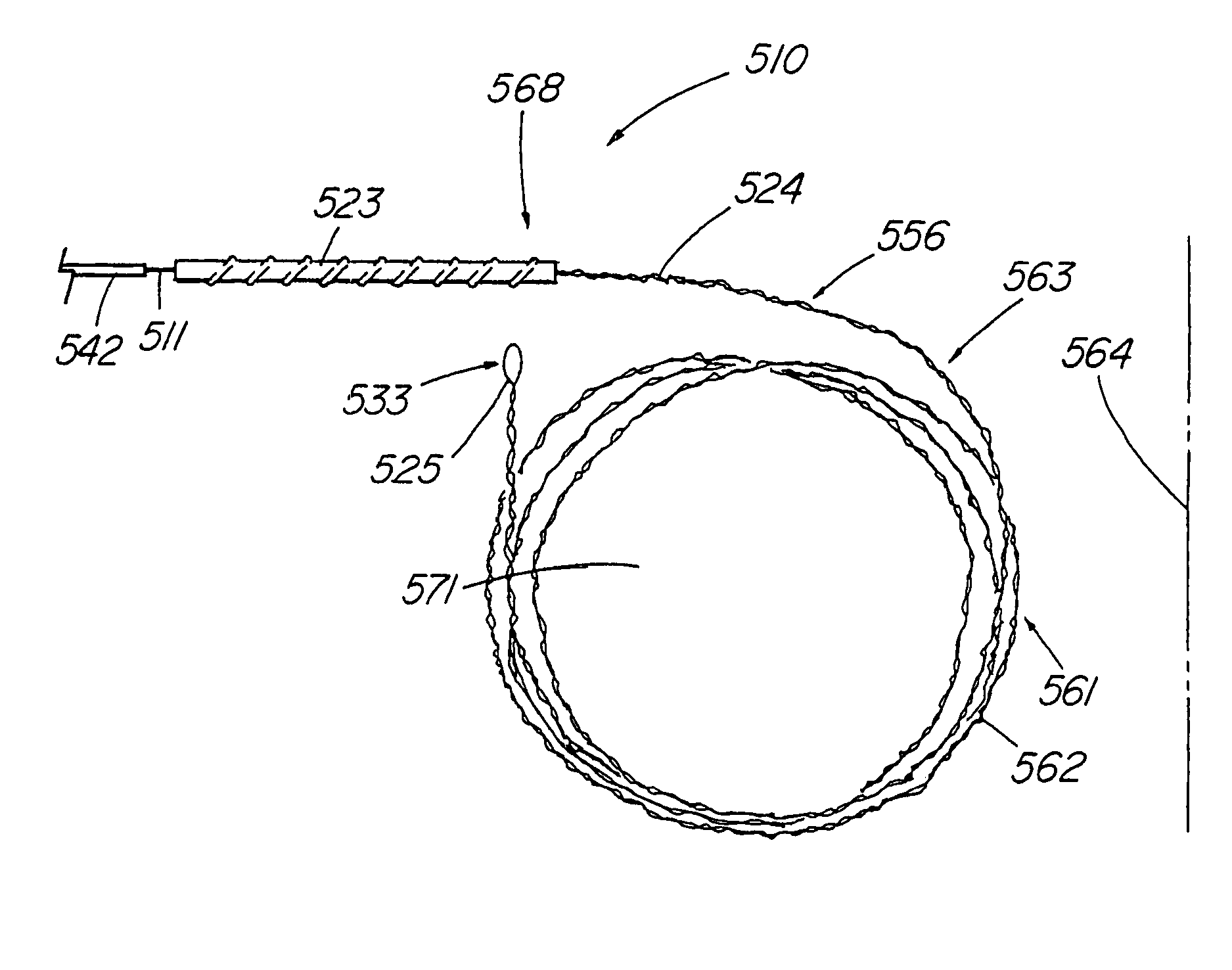
[0042]The foregoing problems are solved and a technical advance is achieved in a lead apparatus, wherein the handle of the lead removal apparatus includes a proximal portion of the handle of a lead removal apparatus which is formed into a pre-shaped first configuration, such as a series of coiled loops. The coiled loops provide the operator with a greater ability to apply traction on the locking stylet and pacemaker lead and helping to maintain the proximal portion of the apparatus within the sterile field. The proximal portion can constrained into a second, sufficiently straight configuration that allows the operator to feed a medical device, such as a dilator sheath thereover, such as for disrupting scar tissue encasing the lead along the path of the vein.

Problems solved by technology

However, one problem is that, over time, fibrotic tissue commonly encapsulates the pacemaker lead especially in areas where there is low velocity blood flow.
When small diameter veins through which the lead passes become occluded with fibrotic tissue, separating the lead from the vein is difficult and causes severe damage or destruction of the vein.
Furthermore, the separation is usually not possible without restricting or containing the movement of the pacemaker lead.
One problem with leaving an implanted lead in place, particularly in the heart, is that the lead actually restricts the operation of the various heart valves through which the lead passes.
If several leads passing through a heart valve are left in place, the operation of the heart valve and the efficacy of the heart is significantly impaired.
Another problem associated with leaving a pacemaker lead in place, particularly in blood vessels, is that an infection may develop in or around the lead, thereby requiring surgical removal.
Surgical removal of the lead from the heart often involves open heart surgery with accompanying complications, risks, and significant cost.
However, when the lead cannot be removed because of some complication, a serious problem is that the tip of the tool is locked in place and cannot be removed from the lead.
Furthermore, the rigid tube of the tool can easily puncture a blood vessel or, even worse, a heart cavity wall.
Even then, this method has a number of problems.
First, when the polyurethane or silicon insulation surrounding the wire coil is damaged, the insulation can sever and cause the coiled structure of the lead to unwind and possibly to damage the heart and surrounding blood vessels.
Secondly, when both the coiled structure and insulation are severed in the heart or a blood vessel, surgical removal is required.
For fibrotic tissue that has encapsulated the tip, unaided manual removal of the heart lead from the heart cavity wall may cause an inward extension or inversion of the wall, or even worse, permanent damage to the heart such as tearing a hole in the heart cavity wall.
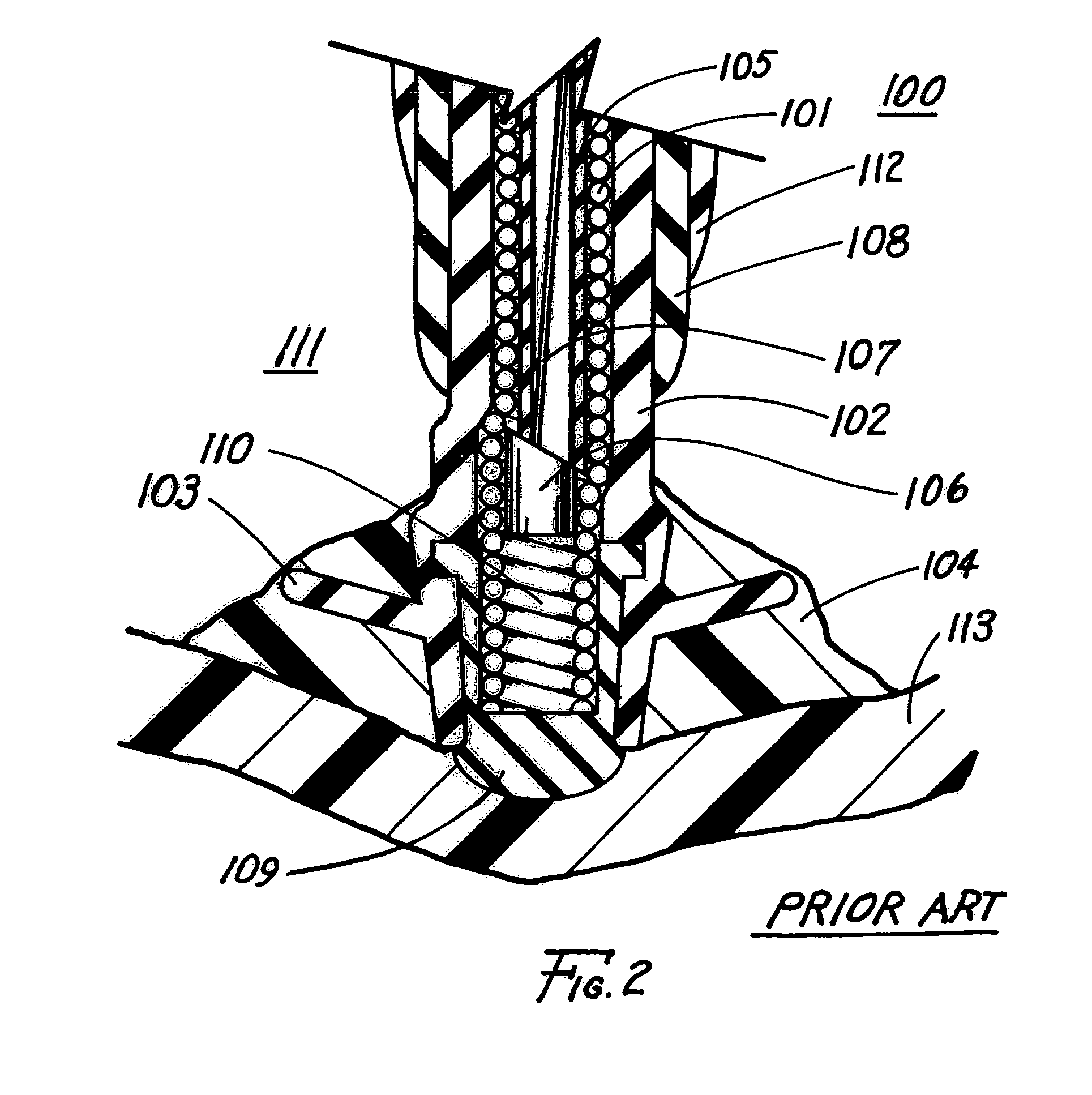
While the use of a radially expandable wire coil at the distal end of a stylet is an effective method of securing the pacemaker lead near the electrode tip, failure to engage has been observed in a number of cases.
Nevertheless, behavior of the wire coil during expansion can be unpredictable so that even when the correct locking stylet is selected, adequate engagement with the lead coil often cannot be achieved, or the two can separate during traction to free the lead.
While often this may occur due to improper locking technique on the part of the physician, often the failure is purely mechanical.
Many times, a second locking stylet can be used successfully, but this results in increased material costs and risk to the patient due to the lengthening of the procedure.
Another disadvantage of currently available systems is that array of different sized stylets must be used for the wide range of pacemaker electrode sizes, normally 0.016 to 0.032'″.
Having to properly size the coil for selection of the optimal stylet adds time, cost, and the potential for error to the procedure.

Method used


Image

  • Method of removing an elongated structure implanted in biological tissue
  • Method of removing an elongated structure implanted in biological tissue
  • Method of removing an elongated structure implanted in biological tissue

Examples


fourth embodiment

[0094]Depicted in FIG. 13 is illustrative removal apparatus 1301 inserted in the longitudinal passageway 210 of coiled structure 211. Removal apparatus 1301 includes a control tube 1302 having a distal end with a spiral or helical ridge 1303 formed therein. Alternatively, a number of barbs are formed in the contoured distal end of control tube 1302. The distal end includes a plurality of slits 1307 or an opening thereat for expanding the ridge or barbs into the coiled structure. Actuator rod 1304 is inserted into passageway 1305 to engage the distal end. When engaged, actuator rod expands the ridge or barbs in a radial direction, as shown by arrows 1308, to engage the coiled structure of the pacemaker lead. As a result, the expanded ridge or barbs secure the control tube to the coiled structure for controlling the movement thereof.

fifth embodiment

[0095]Depicted in FIG. 14 is illustrative removal apparatus 1401 inserted in longitudinal passageway 210 of coiled structure 211. The removal apparatus includes control tube 1402 and actuator rod 1403 extending through hollow passageway 1404 of the control tube. The apparatus also includes a diagonally-slotted sleeve 1405 that is positioned between the distal ends of the control tube and actuator rod. The actuator rod also extends through hollow passageway 1406 of the sleeve. Attached to the distal end of the actuator rod is beveled tip 1407 having an outside diameter approximating the diameter of the control tube and the nominal diameter of the slotted sleeve. Similarly, the distal end of the control tube is beveled to engage and expand the slotted sleeve. To expand the slotted sleeve, the actuator rod is pulled, as indicated by arrow 1408, to engage the sleeve against the beveled edges of the control tube and the rod. As a result, the sleeve is expanded to a position for engaging ...


PUM


Abstract

Disclosed is a lead removal apparatus for removing an implanted pacemaker or defibrillator lead from the heart. The lead removal apparatus includes a proximal handle that further includes a proximal portion, such as an elongate section of intertwined wire, having a compact, pre-formed first configuration, such as one or more coiled loops. The compact shape permits the operator to utilize the proximal portion without requiring the assistance of a second person to help keep it within the sterile field during a procedure. The operator is thus able to constrain or uncoil the proximal portion into a second configuration that is sufficiently straight such that a medical device, such as a dilator sheath, can be advanced thereover to help separate the lead from scar tissue along the vein path. The proximal portion may include sufficient resiliency to substantially return to the first configuration once the sheath has been advanced.

Description

CROSS-REFERENCE TO RELATED APPLICATIONS[0001]This application is a division of application Ser. No. 09 / 859,555, filed May 17, 2001 now U.S. Pat. No. 6,687,548, which is hereby incorporated by reference herein.[0002]This application claims priority of provisional application Ser. No. 60 / 204,652, filed May 17, 2000.TECHNICAL FIELD[0003]This invention relates to elongated structures, such as a catheter implanted in tissue or an electrical pacemaker or defibrillator lead implanted in or on the heart and, particularly, to apparatus for removing such elongated structures implanted in biological tissue.BACKGROUND OF THE INVENTION[0004]A heart pacemaker is generally implanted subcutaneously in the chest wall along with a coiled structure such as an electrical wire coil lead for conducting electrical signals such as stimulating and sensing signals between the pacemaker and the heart. The lead is surgically implanted through a vein leading to a cavity of the heart. A typical lead includes one...

Claims


Application Information

Patent Timeline
IPC IPC(8): A61N1/05A61N1/372A61B17/00A61M25/01A61M25/02A61N1/39
CPCA61N1/056A61N1/057A61N2001/0578
Inventor GOODE, LOUIS B.
Owner COOK MEDICAL TECH LLC
Learn More