Method of sealing a well

a well and well sealing technology, applied in the direction of drilling casings, drilling pipes, borehole/well accessories, etc., can solve the problems of associated safety risks, costly and time-consuming tubing removal exercise, etc., and achieve the effect of high viscosity

Active Publication Date: 2016-08-11
DEN NORSKE STATS OLJESELSKAP AS
View PDF5 Cites 3 Cited by
  • Summary
  • Abstract
  • Description
  • Claims
  • Application Information

AI Technical Summary

Benefits of technology

[0012]It will be understood that a stinger is normally a piece of tubular which is provided on a lowermost section of a tubing string to sting into another section of tubular (or a fluid or a seal) in order to perform a task such as sealing, pumping, verifying a location or opening valves etc. Alternatively, a small diameter tubing may be inserted along the entire length of the tubing. It is therefore an advantage of the present invention that the stinger is located only in the area of interest using wireline, thereby reducing the time and cost for the operation.
[0013]The stinger may have a fixed length or may be extendable. The length of the stinger may depend upon on the lubrication length available and / or the length of the interval to be sealed off.
[0014]In certain embodiments, the stinger may be telescopic. In which case, a plurality of telescopic sections may be held in a compacted configuration by a mechanism (e.g. shear screws, latches, detent rings, etc.) configured to release when a pre-determined pressure is applied, thus causing the telescopic sections to extend. Seals (e.g. O-rings or the like) may be provided between each telescopic section to ensure the joins are fluid-tight.
[0015]The telescopic stinger may comprise a valve across an end which is lowermost when the stinger is extended. The valve may be configured to adopt a closed position when fluid is pumped down into the stinger to apply pressure to the release mechanism to open each telescopic section. Once the stinger is suitably (e.g. fully) expanded, a greater pressure may be applied (e.g. above hat required to release the mechanism) in order to open the valve for pumping sealant into the tubing and casing.
[0016]The one or more openings may be formed by removing a relatively large section of the tubing (e.g. by milling). Alternatively, the one or more openings may be formed by slicing or perforating one or more holes in a section of the tubing.
[0017]The method may further comprise the use of a high viscous pill deployed through the stinger to clean the location before forming the seal.

Problems solved by technology

However, the removal of the tubing is a costly and time-consuming exercise as it requires a drill rig on site.
There also associated safety risks.

Method used


Image

  • Method of sealing a well
  • Method of sealing a well
  • Method of sealing a well

Examples


Embodiment Construction

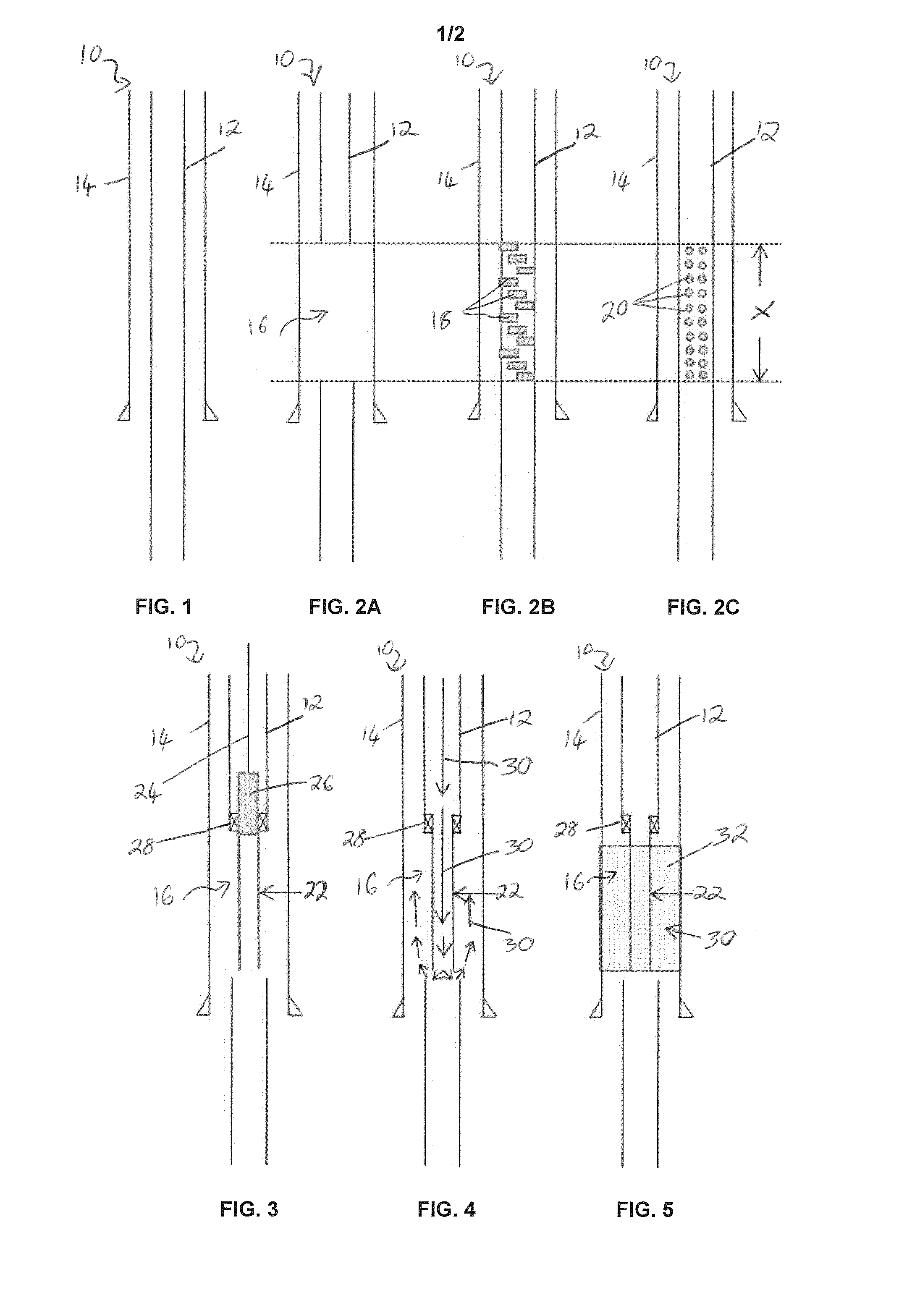
[0036]FIGS. 1 to 5 illustrate various methods for sealing a well in accordance with embodiments of the present invention.

[0037]As shown in FIG. 1, a wellbore 10 is provided with a production tubing 12 extending through a casing 14 to form a so-called A-annulus there-between. One or more openings is created in the tubing 12, in a location X for a well seal, as illustrated in the alternative FIGS. 2A, 2B and 2C.

[0038]FIG. 2A illustrates the case where a relatively large section of the tubing 12 has been removed to create a single opening 16 extending over the entire location X for the well seal, in accordance with one embodiment of the invention.

[0039]FIG. 2B illustrates the case where a plurality of openings 18 have been sliced in the tubing 12, in the location X for the well seal, in accordance with another embodiment of the invention.

[0040]FIG. 2C illustrates the case where a plurality of openings 20 have been perforated or punched in the tubing 12, in the location X for the well s...


PUM


Abstract

A method of sealing a well comprises creating one or more openings in a tubing installed in a wellbore, in a location for a well seal; using a wireline to locate a stinger in that location; setting the stinger in that location; and forming a seal in the well in that location, by injecting sealant through said stinger.

Description

FIELD OF THE INVENTION[0001]The present invention relates to a method of sealing a well. In particular embodiments, the method comprises installing a permanent fluid-tight barrier for well abandonment.BACKGROUND TO THE INVENTION[0002]Traditional plug and abandonment operations require that the entire production tubing and associated cabling is pulled from the wellbore prior to installation of a cement plug. However, the removal of the tubing is a costly and time-consuming exercise as it requires a drill rig on site. There also associated safety risks.[0003]It is therefore an aim of the present invention to provide an alternative method of sealing a well which helps to address the afore-mentioned problems.SUMMARY OF THE INVENTION[0004]In accordance with a first aspect of the present invention there is provided a method of sealing a well comprising:[0005]creating one or more openings in a tubing installed in a wellbore, in a location for a well seal;[0006]using a wireline to locate a ...

Claims


Application Information

Patent Timeline
Patent Type & Authority Applications(United States)
IPC IPC(8): E21B33/13E21B34/06E21B17/00
CPCE21B33/13E21B34/06E21B17/00E21B33/134E21B33/10
Inventor HEMMINGSEN, PÅL VIGGOGRIMSBO, GJERMUNDBUCHANAN, ALASTAIR
Owner DEN NORSKE STATS OLJESELSKAP AS
Why Eureka
Try Eureka