Smart home-care lighting system

a home-care lighting and smart technology, applied in the field of smart home-care lighting apparatus, can solve the problems of inconvenient use, short detection range, difficult applications in a household or interfering environment, etc., and achieve the effect of improving personal health information, low accuracy, and convenient and convenient us

Inactive Publication Date: 2016-08-11
CHEN KAIPO
View PDF1 Cites 22 Cited by
  • Summary
  • Abstract
  • Description
  • Claims
  • Application Information

AI Technical Summary

Benefits of technology

[0007]The present invention provides a lighting device that is combined with multiple techniques of detection and remote surveillance and monitoring to improve, fundamentally, detection functions having low accuracy for integration with electrical appliances commonly used in a household environment and to determine physical conditions of a person through the system for combination with corresponding devices such that the present invention combined with the lighting device provides a multifunctional household surveillance and monitoring system, which is easy and convenient in actual applications.
[0008]The present invention provides a smart home-care lighting system, which comprises a lighting device comprising a cover of which at least a portion is light transmittable. The lighting device is provided, in the interior thereof, with an illumination module for purpose of lighting, an image pickup module for capturing images in non-overlapping ranges, a detection module for detecting environment conditions, an alarm module for indicating and notifying the detected environment conditions, and a sound effect module. These modules are electrically connected to a main control module. The main control module comprises a chip for transmission of information in order to establish connection with for example a tablet computer, a sma

Problems solved by technology

Such a system needs an additional device used in combination therewith, making it imperfect and inconvenient in use.
However, a major drawback is that efficient and accurate detection

Method used


Image

  • Smart home-care lighting system
  • Smart home-care lighting system
  • Smart home-care lighting system

Examples


Embodiment Construction

[0025]The following descriptions are exemplary embodiments only, and are not intended to limit the scope, applicability or configuration of the invention in any way. Rather, the following description provides a convenient illustration for implementing exemplary embodiments of the invention. Various changes to the described embodiments may be made in the function and arrangement of the elements described without departing from the scope of the invention as set forth in the appended claims.

[0026]Better understanding of the present invention can be achieved according to a general detailed description of the present invention, as well as a preferred feasible embodiment thereof, in combination with the attached drawings. The present invention provides a smart home-cue lighting system.

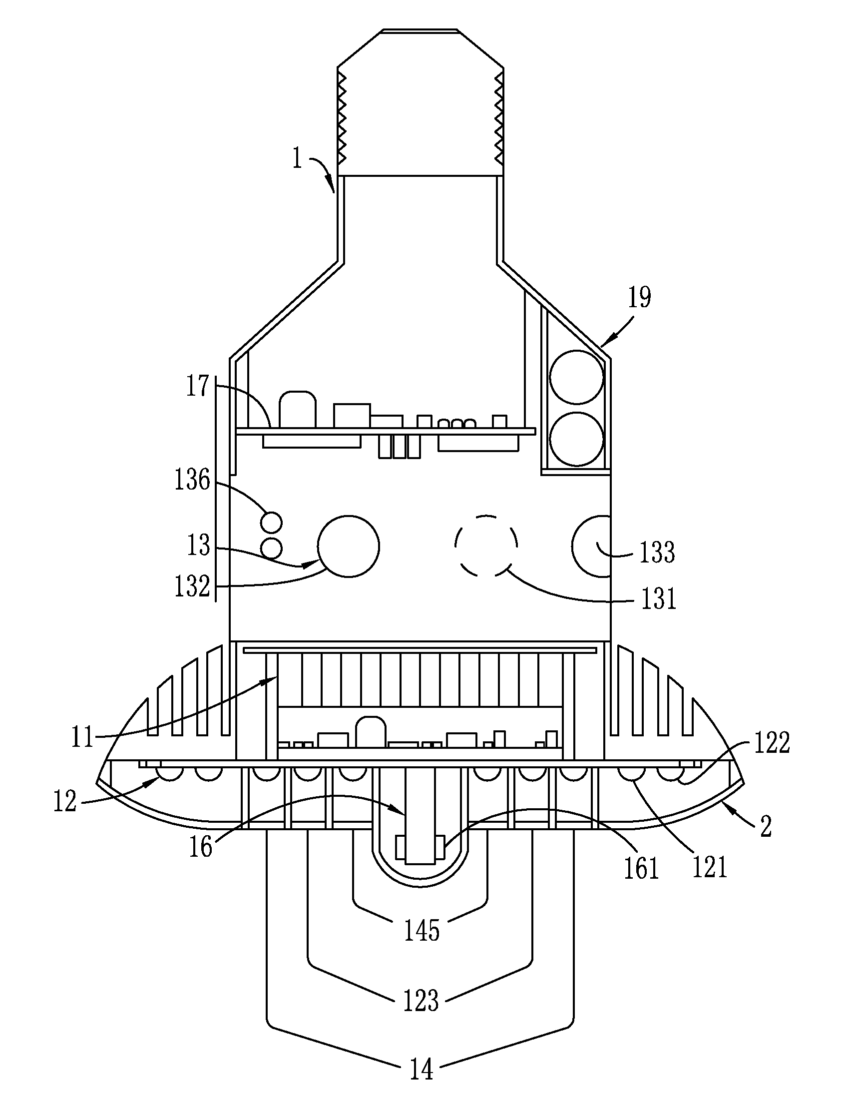
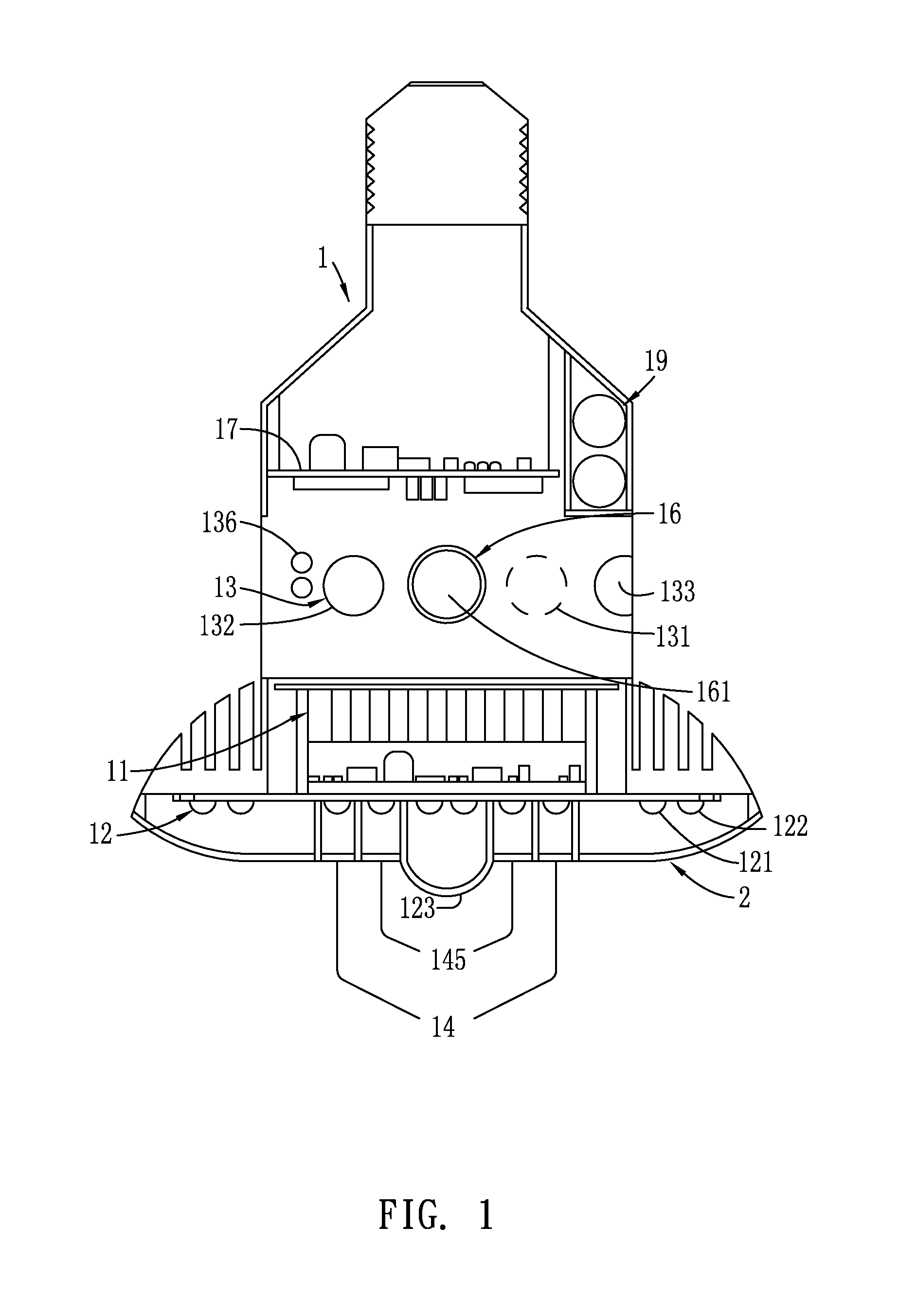
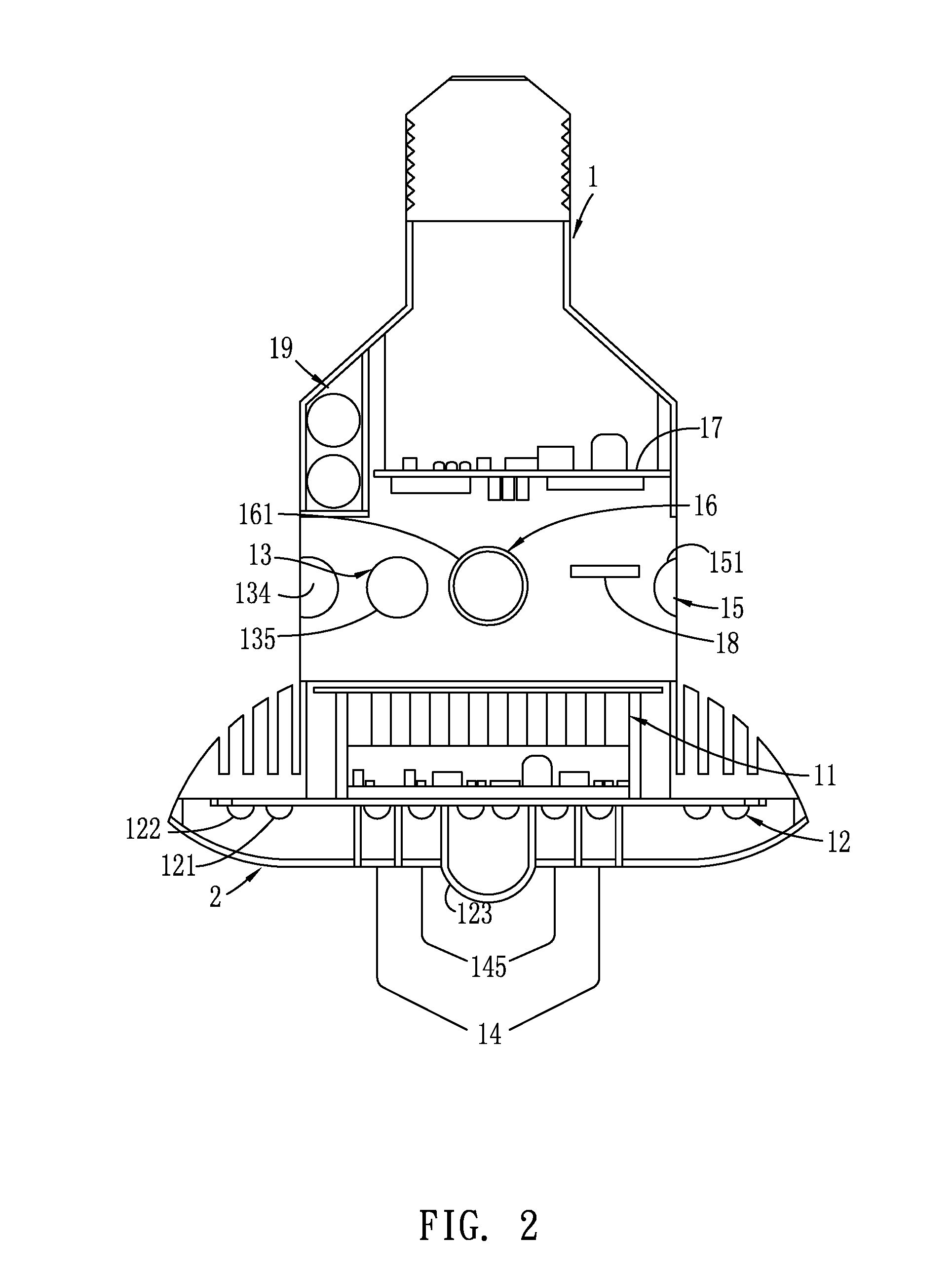
[0027]Shown in FIGS. 1-3 comprise: a lighting device (1), of which at least a part comprises a cover (2) that is light transmittable, the cover (2) being integrally formed with the lighting device (1), or be...


PUM


Abstract

A smart home-care lighting system includes a lighting device having a portion that is light transmittable. The lighting device receives therein an illumination module for purpose of illumination, a detection module for detecting an outside environment, an alarm module and a sound effect module operable in combination with the detection module for indication and alarming, and an image pickup module for capturing and recording images. The lighting device also includes, arranged therein, a microprocessor and a main control module for transmitting and storing personal habits and health information. The device is arranged such that image can be captured in ranges that does not overlap to provide a surveillance range of 360-degree full view and operation can be made with the main control module for determination for proper action to be taken and may be used in combination with household appliances to construct a smart home-care system that benefit home members.

Description

CROSS-REFERENCE TO RELATED APPLICATION[0001]This is a continuation-in-part of co-pending U.S. patent application Ser. No. 14 / 258,029 filed on Apr. 22, 2014 and owned by the present applicant.TECHNICAL FIELD OF THE INVENTION[0002]The present invention relates generally to a smart home-care lighting apparatus, in which an image pickup module capable of recognizing a target in a range of 360 degrees is involved in order to integrate a function of environment detection condition and allows for using lighting and sound for alarming and indication to provide better protection to the living of family members.DESCRIPTION OF THE PRIOR ART[0003]With the light-emitting diode (LED) technology getting mature in various applications, in addition to the development of techniques regarding energy saving and lighting, manufacturers also focus on the development of styles and functions of LED related devices available in the market to provide multiple functions associated therewith.[0004]The progress...

Claims


Application Information

Patent Timeline
IPC IPC(8): H04N5/225F21V33/00G08B7/06H04N7/18G08B13/196F21V23/00H05B37/02
CPCH04N5/2252F21Y2113/005H04N7/183H04N5/2257F21V23/003F21V33/0076H05B37/0227H05B37/0272F21V33/0056H04N7/181F21V33/0052G08B13/19619G08B7/06F21Y2101/02H04N5/2256F21S8/026F21S8/061F21S9/024F21K9/233F21Y2115/10F21Y2113/10G08B17/00G08B19/005G08B21/043G08B21/0469G08B25/14F21V23/005F21V23/006F21K9/238H05B47/19H05B47/165H05B47/125H05B47/195Y02B20/40H04N23/56H04N23/51F21V23/004H04N7/18F21Y2105/18F21S8/04H05B47/12H05B47/175
Inventor CHEN, KAIPO
Owner CHEN KAIPO
Why Eureka
Try Eureka