Automatic trimmer head

a technology of automatic trimming and trimmer head, which is applied in the field of trimmer head, can solve the problems of reducing the moment of inertia of the head, increasing the rotational speed, and lengthening the protruding wire portions, and achieves the effects of simplifying and speeding up the replacement operation of the cutting wire spool, especially lightweight and compa

Active Publication Date: 2016-08-18
TECOMEC
View PDF0 Cites 15 Cited by
  • Summary
  • Abstract
  • Description
  • Claims
  • Application Information

AI Technical Summary

Benefits of technology

[0006]It is an object of the present invention to provide a trimmer head which allows to overcome the drawbacks of the heads available at present.
[0007]One advantage of the trimmer head is that replacement operations of the cutting wire spool are simplified and speeded up.
[0008]Another advantage of the trimmer head is that it is particularly lightweight and compact.

Problems solved by technology

The shortening of such portions reduces the moment of inertia of the head, which consequently increases its rotational speed.
The activation of the unwinding device causes a lengthening of the protruding wire portions and an increase of the moment of inertia of the head.

Method used


Image

  • Automatic trimmer head
  • Automatic trimmer head
  • Automatic trimmer head

Examples


Embodiment Construction

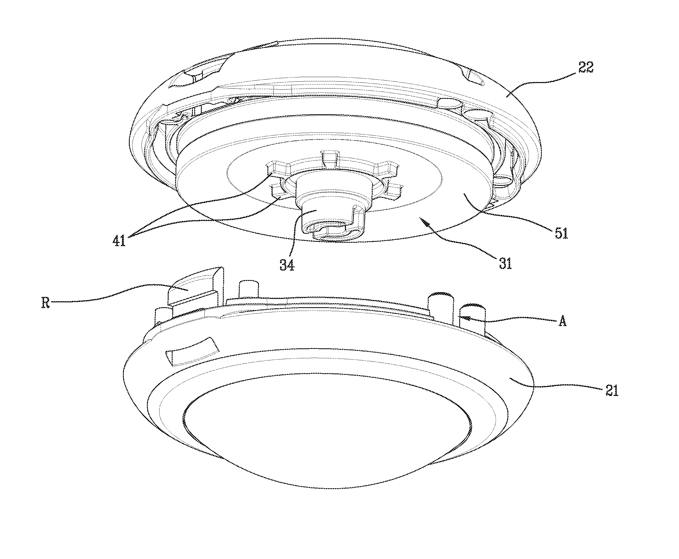
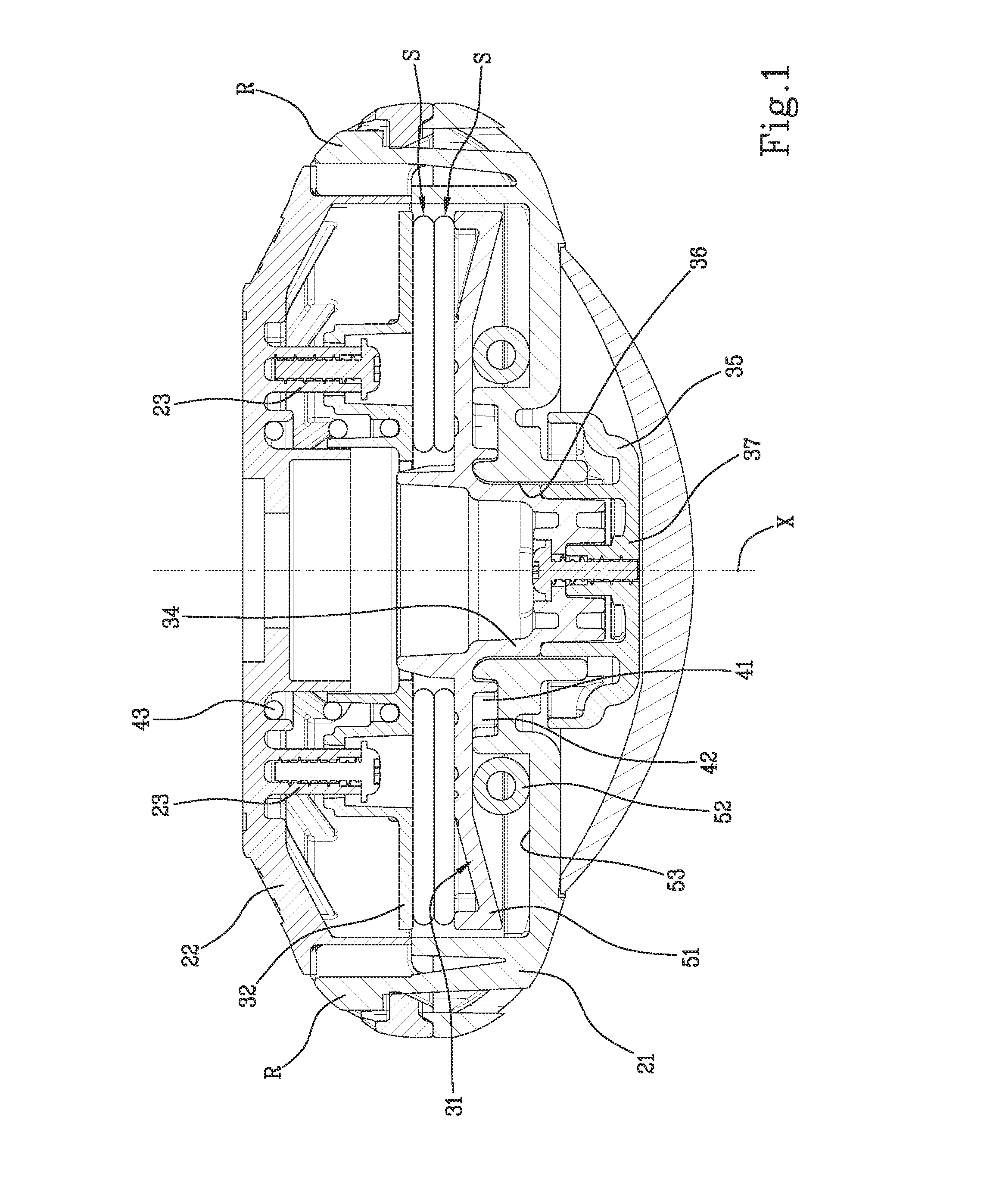
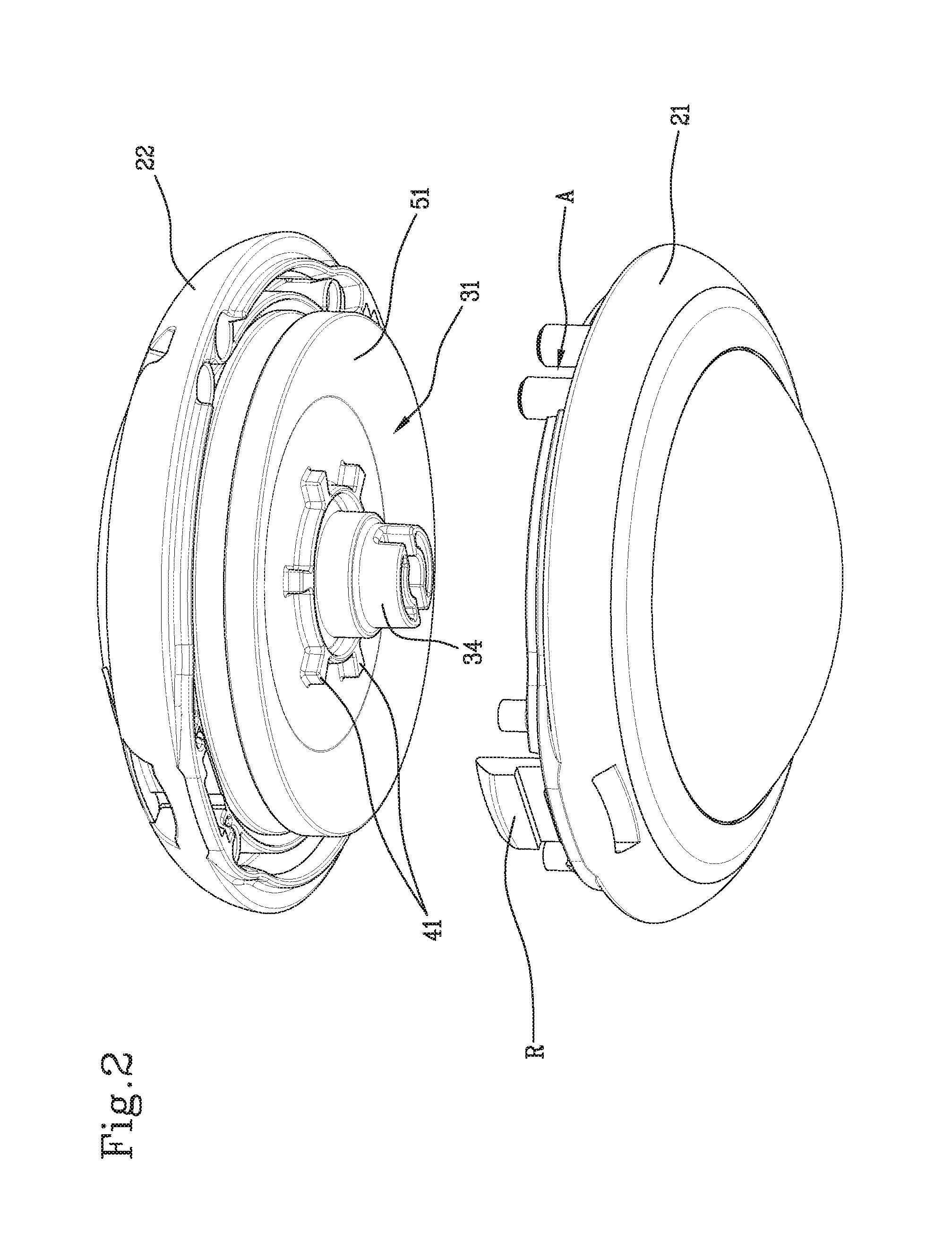
[0014]The head according to the present invention comprises a casing (21, 22), designed to be coupled to a driveshaft for rotating about a main axis (X). The casing (21, 22) is provided with one or more openings (A) in order to afford passage of respective end portions of the cutting wire (W). A supporting device (31, 32) for a cutting wire spool is housed inside the casing (21, 22).

[0015]The supporting device (31, 32) is movable between an engagement position, wherein it is rotatingly solid with the casing (21, 22), and a free position, wherein it is not rotatingly solid with the casing (21, 22). In a known manner, in the free position of the supporting device (31, 32), a relative rotation between the casing (21, 22) and the supporting device (31, 32) itself is produced during rotation of the head. This relative rotation is aimed at causing unwinding of a given portion of the cutting wire owing to which the portions that became detached during use can be restored.

[0016]Coupling mea...


PUM


Abstract

A trimmer head, comprising: a casing 21, 22, a supporting device 31, 32 for a cutting wire spool, which supporting device (31, 32) is arranged within the casing (21, 22) and movable between an engagement position, wherein it is rotatingly solid with the casing (21, 22), and a free position, wherein it is not rotatingly solid with the casing (21, 22). The head further comprises coupling means 41,42, which are so configured as to make the casing (21, 22) and the supporting device (31, 32) rotatingly solid with one another in the engagement position, engagement means (43) which are so configured as to allow displacement of the supporting device (31, 32) from the free position to the engagement position and release means (51, 52) configured for moving the supporting device (31) from the engagement position to the free position, said release means (51, 52) being activated under the effect of the centrifugal force due to rotation of the trimmer head. The supporting device 31 comprises a lower disk (31) and an upper disk (32) which are independent of one another.

Description

FIELD OF THE INVENTION[0001]The present invention has for an object a trimmer head. The invention particularly relates to a head provided with an automatic cutting wire unwinding device.BACKGROUND OF THE INVENTION[0002]Several examples of heads of this type are currently available on the market. These heads comprise a casing internally of which a winding-reel is housed for winding a wire cutting spool. Two portions of the cutting wire protrude outwardly the casing through dedicated openings. The winding-reel is associated to the casing and can take on an engagement position, wherein it is rotatingly solid with the casing, and a free position, wherein it can rotate with respect to the casing. Notoriously, the free position of the winding-reel is exploited to cause unwinding of the wire spool with the purpose of restoring the length of the cutting wire portions which protrude outward of the casing. The automatic cutting wire unwinding device allows essentially to move the winding-reel...

Claims


Application Information

Patent Timeline
Patent Type & Authority Applications(United States)
IPC IPC(8): A01D34/416
CPCA01D34/416A01D34/4166A01D34/4162
Inventor CIGARINI, ENRICOLONGO, SALVATORE
Owner TECOMEC
Why Eureka
Try Eureka