

Endoscopic treatment instrument and endoscope system
a treatment instrument and endoscope technology, applied in the field of endoscope system and endoscope treatment instrument, can solve the problem of increasing the outside diameter of the manipulator
- Summary
- Abstract
- Description
- Claims
- Application Information
AI Technical Summary
Benefits of technology
Problems solved by technology
Method used
Image

Examples
modification 1
[0078]Although in the embodiment described above, air is supplied from the sheath member 51 to the sheath member 47 through the gap G formed between the inner circumferential face of the connection ring 50 and outer circumferential face of the fixing member 54, air may be supplied from the sheath member 51 to the sheath member 47 through a hole provided in the fixing member.
[0079]FIG. 5 is a sectional view of a connecting portion between the sheath members 47 and 51 connected by a fixing member 54A in modification 1. The fixing member 54A is shaped like a pipe and provided with a ring-shaped protrusion 81 in a central portion, protruding radially outward. Sandwiching the protrusion 81, the sheath members 47 and 51 are fitted over a stepped portion and fixed by adhesive, where the stepped portion is formed by the protrusion 81 of the fixing member 54A.
[0080]The fixing member 54A has a partition wall 83 in a central portion, where the partition wall 83 is provided with plural air vent...
modification 2
[0096]Whereas in the embodiment and modification 1 described above, when air is supplied into the sheath member 47 and the air is fed to a distal end side of the sheath member 47, the wire 45 and rod 71 are pushed out by the air, in modification 2, the wire 45 is further provided with an air receiving member configured to receive pressure of the air flowing through the sheath member 47.
[0097]FIG. 7 is a sectional view of a treatment unit 21 according to modification 2. As shown in FIG. 7, an air receiving member 74 is provided at a midpoint on the wire 45. The air receiving member 74 is a disk-shaped member with an outside diameter smaller than an inside diameter of the sheath member 47 and is fixed to the wire 45. That is, the air receiving member 74 is provided on an outer surface of the wire 45 which is a linear member and is a gas receiving unit configured to receive gas flowing from the proximal end side to distal end side of the sheath 22.
[0098]Air hits the air receiving membe...
modification 3
[0100]Whereas in the embodiment and modifications 1 and 2 described above, the wire 45 and the like are pushed out to the distal end side of the sheath member 47 by the air sent to the sheath member 47, if pressure of the air is disturbed, excessive air pressure might be applied to the treatment unit 21. Therefore, an endoscopic treatment instrument according to modification 3 is designed such that the pressure in the sheath member 47 will fall when the wire 45 and the like move a predetermined amount.
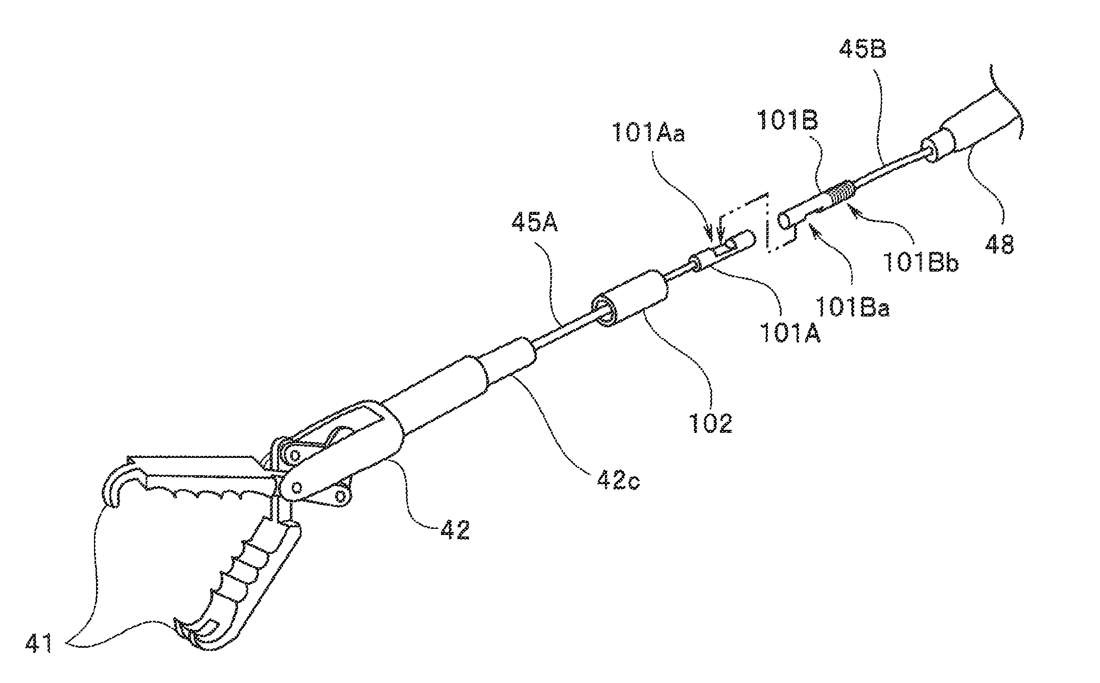
[0101]FIG. 8 is a partial sectional view of the treatment unit 21 in a state in which the wire 45 is being pulled by the actuator 48 in modification 3. In modification 3, the rod 71A passed through the hole 42b formed in the proximal end portion of the support member 42 has an expanded-diameter portion 71Aa on the distal end side. That is, the rod 71A, which is a rod member connected to the treatment unit 21 has the expanded-diameter portion 71Aa on the distal end side, where the expan...
PUM
 Abstract
Description
Claims
Application Information