
Accident monitoring using remotely operated or autonomous aerial vehicles

a technology of remote operation or autonomous aerial vehicles, applied in simultaneous traffic control systems, television systems, instruments, etc., can solve problems such as vehicle accidents, billions of dollars a year, and the danger of driving a vehicl

Active Publication Date: 2016-08-18
SCOPE TECH HLDG
View PDF4 Cites 107 Cited by
  • Summary
  • Abstract
  • Description
  • Claims
  • Application Information

AI Technical Summary

Benefits of technology

This patent describes a system and method for detecting and analyzing accidents involving vehicles. The system uses sensors within the vehicle or attached to it, along with additional sensors that can be part of a portable device or stationary sensors, to capture data on the vehicle's movements and driving behavior. This data is then analyzed using techniques such as image analysis, statistics, and machine learning to estimate the damage and extent of the accident. The system can also anticipate accidents and make recommendations for emergency response. The goal is to provide a more reliable and accurate way to assess accidents and make them a safer part of everyday life.

Problems solved by technology

Driving a vehicle continues to be one of the most hazardous activities that a person can participate in.
Vehicle accidents are one of the leading cause of death every year.
Damage from accidents amounts to billions of dollars a year.
This human interface introduces many biases and uncertainties into the process.
These biases and uncertainties then translate into litigation when it is necessary to determine cause for insurance purposes or from a safety standard.
However, the changing regulatory atmosphere makes reliance on any one type of surveillance method risky from the fact that it may be illegal in the near future.
For this reason and others, data fusion among several sensor arrays is important to any vehicle or accident scene surveillance system as certain methods may not be allowed in the long run.

Method used


Image

  • Accident monitoring using remotely operated or autonomous aerial vehicles
  • Accident monitoring using remotely operated or autonomous aerial vehicles
  • Accident monitoring using remotely operated or autonomous aerial vehicles

Examples


Embodiment Construction

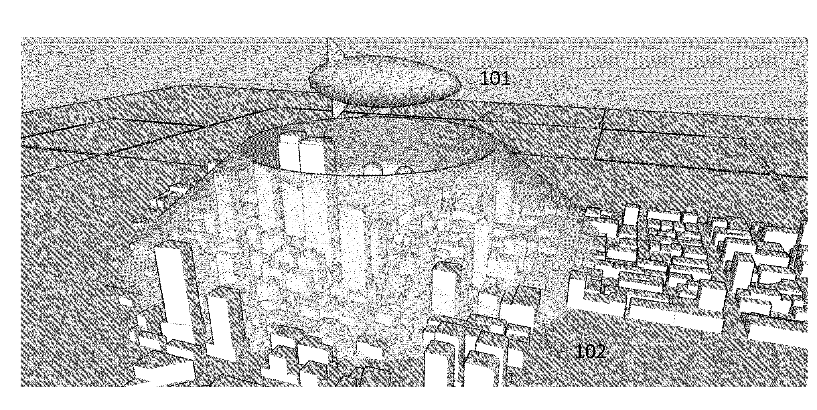
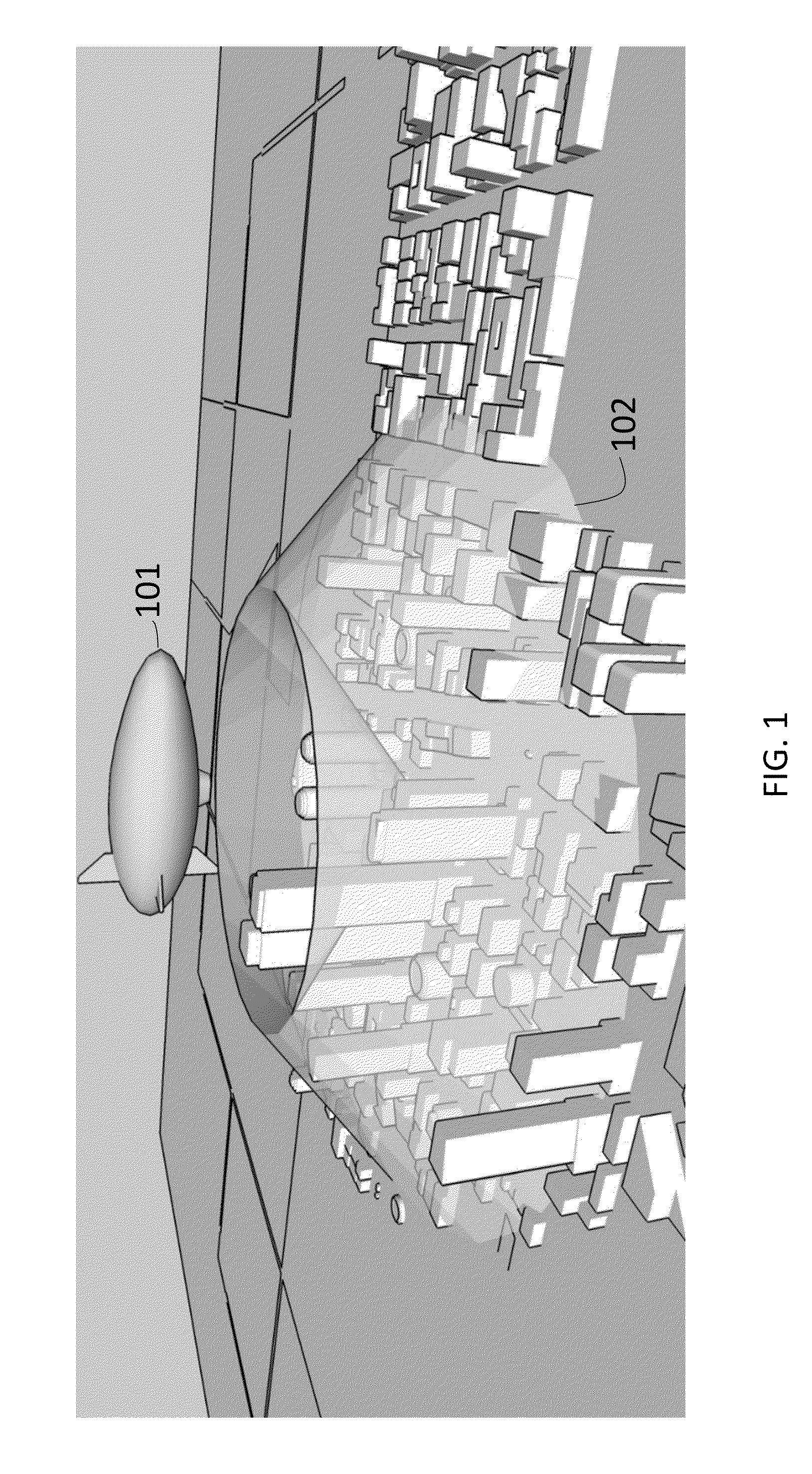
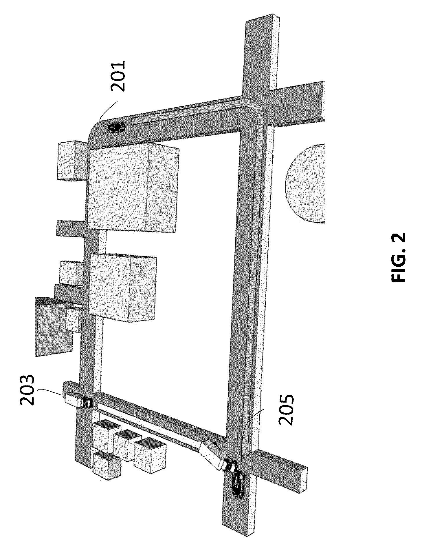
[0254]In an embodiment, a vehicle accident surveillance network comprises at least one of:[0255]a) one or more surveillance systems which in turn comprises:[0256]i) a sensor suite configured to observe ground based vehicles;[0257]ii) a pattern recognition module configured to interpret the sensor suite readings as vehicle movements, locations, pending accidents, and accident incidents and to identify specific vehicles; and[0258]iii) a wireless transceiver configured to transmit and receive the identity and location of specific vehicles that had pattern identified, to surveillance systems;[0259]b) one or more deployable aerial surveillance systems comprising:[0260]i) an airframe configured to launch from one of a ground based vehicle, and fixed base station, and a larger airframe, wherein a launch is triggered by detection of a pattern indicative of an accident occurring or about to occur as detected by one or more of the surveillance systems;[0261]ii) a second wireless transceiver c...


PUM


Abstract

A system to monitor vehicle accidents using a network of aerial based monitoring systems, terrestrial based monitoring systems and in-vehicle monitoring systems is described. Aerial vehicles used for this surveillance include manned and unmanned aircraft, satellites and lighter than air craft. Aerial vehicles can also be deployed from vehicles. The deployment is triggered by sensors registering a pattern in the data that is indicative of an accident that has happened or an accident about to happen.

Description

1 RELATED APPLICATIONS[0001]This application claims priority to U.S. Provisional Application 62 / 109,434 filed on 29 Jan. 2015 and entitled ACCIDENT MONITORING USING REMOTELY OPERATED OR AUTONOMOUS AERIAL VEHICLES which is herein incorporated by reference.[0002]U.S. patent application titled “SYSTEM AND METHOD FOR USE OF PATTERN RECOGNITION IN ASSESSING OR MONITORING VEHICLE STATUS OR OPERATOR DRIVING BEHAVIOR”, application Ser. No. 13 / 679,722, filed Nov. 16, 2012; which claims the benefit of priority to U.S. Provisional Patent Application No. 61 / 578,511, filed Dec. 21, 2011; PCT / US12 / 71487 titled “SYSTEMS AND METHODS FOR ASSESSING OR MONITORING VEHICLE STATUS OR OPERATOR STATUS” filed 21 Dec. 2012; and Ser. No. 14 / 317,624 titled “System and method for Determining Of Vehicle Accident information” file on 27 Jun. 2014; each of which the above applications are herein incorporated by reference.2 INTRODUCTION[0003]Aspects of this invention are designed to provide as close to real-time su...

Claims


Application Information

Patent Timeline
Patent Type & Authority Applications(United States)
IPC IPC(8): B60R21/0132G06K9/00B64C39/02H04N7/18G06V20/00
CPCB60R21/0132H04N7/185B60R2021/0027B64C39/024B64C2201/127G06K9/00771G08G1/0112G08G1/0116G08G1/012G08G1/0133G08G1/04G08G1/065G08G1/205G08G7/00G06V20/00G06V20/52G06V20/17B64U10/30B64U2101/31B64U10/14B64U70/83
Inventor LAVIE, SAMUELFUCHS, GIL EMANUELMORLOCK, CLAYTON RICHARD
Owner SCOPE TECH HLDG
Learn More