Method of centralising tubing in a wellbore

Active Publication Date: 2016-08-18
DEN NORSKE STATS OLJESELSKAP AS
View PDF1 Cites 4 Cited by
  • Summary
  • Abstract
  • Description
  • Claims
  • Application Information

AI Technical Summary

Benefits of technology

[0011]Embodiments of the invention therefore provide a method which can be used to effectively centralise production tubing within a wellbore. It should be noted that when a well is completed, there is currently no method for centralising the tubing without recompleting the well. An advantage of the present method is that it can be used in a retrofit (intervention) operation, preferably on wireline, to centralise existing tubing already installed down-hole.
[0012]It should be noted that the material and/or environment of the tubing may dictate which centralising technique is best. For example, providing one or more expandable elements may be preferred for a more controlled expansion but if penetrating the tubing is required to insert the expandable elements this should only be carried out if penetration of the tubing is considered safe (e.g. if the tubing is not lying too close to the casing). On the other hand, expanding portions of the tubing itself may be more time-efficient if the tubing is of a suitable material

Problems solved by technology

However, production tubing is not currently centralised within the wellbore and instead tends to lie along the inner casing wall (with metal to metal contact), particularly in sloped portions of a wellbore which may be angled at a gradient of 60-80%.
This configuration will significantly increase the r

Method used


Image

  • Method of centralising tubing in a wellbore
  • Method of centralising tubing in a wellbore
  • Method of centralising tubing in a wellbore

Examples


Example

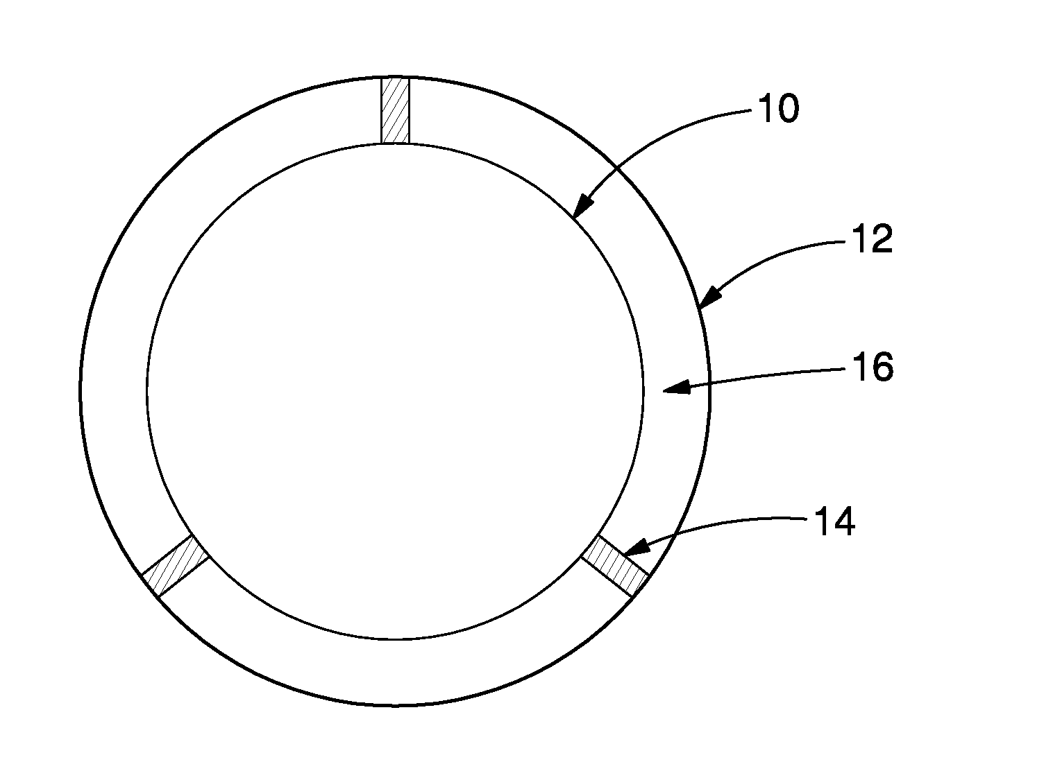
[0040]In accordance with the first embodiment, radial holes are cut in the tubing 10 and the expandable support elements 14 are inserted into the annulus 16 and expanded against the casing 14 to cause the tubing 10 to centralise. In this case, the expandable support elements 14 are configured as mechanical devices that can be operated via wireline.

[0041]Once the tubing 10 is centred, the same holes (or additional holes) may be utilised to flush and clean-out the annulus 16 before a sealant (e.g. cement) is pumped into the annulus 16 to form a plug therein. It will be noted that in this embodiment, the expandable support elements 14 are left in place and the plug is formed around them.

Example

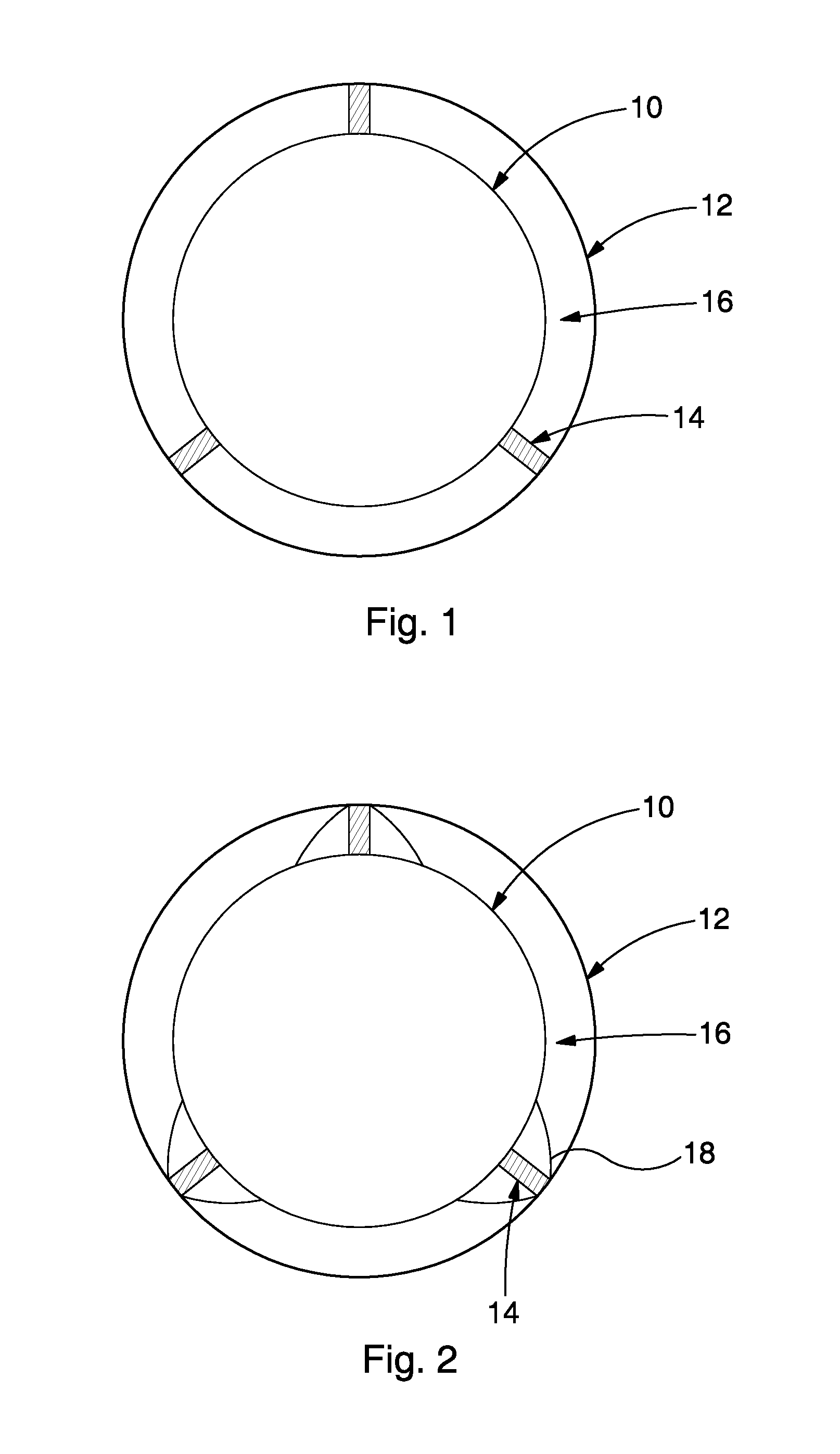
[0042]FIG. 2 shows a second embodiment in which the production tubing 10 is provided with three expandable elements 14 located around the outside of the tubing 10 and retained by an intermediate tubular 18, prior to insertion of the production tubing 10 in the wellbore. The expandable elements 14 in this embodiment are hydraulic pistons which are initially in a collapsed configuration for ease of installation of the production tubing 10 in the casing 12.

[0043]When it is desired to centralise the tubing 10 (e.g. before a plug and abandonment procedure), the expandable elements 14 will be activated using wireline so as to cause the intermediate tubular 18 to be locally expanded against the casing 12.

[0044]Once the tubing 10 is centred, holes may be formed in the production tubing 10 and the intermediate tubular 18 so that a sealant can be pumped into the annulus 16 to form a fluid-tight plug across the entire width of the annulus 16.

Example

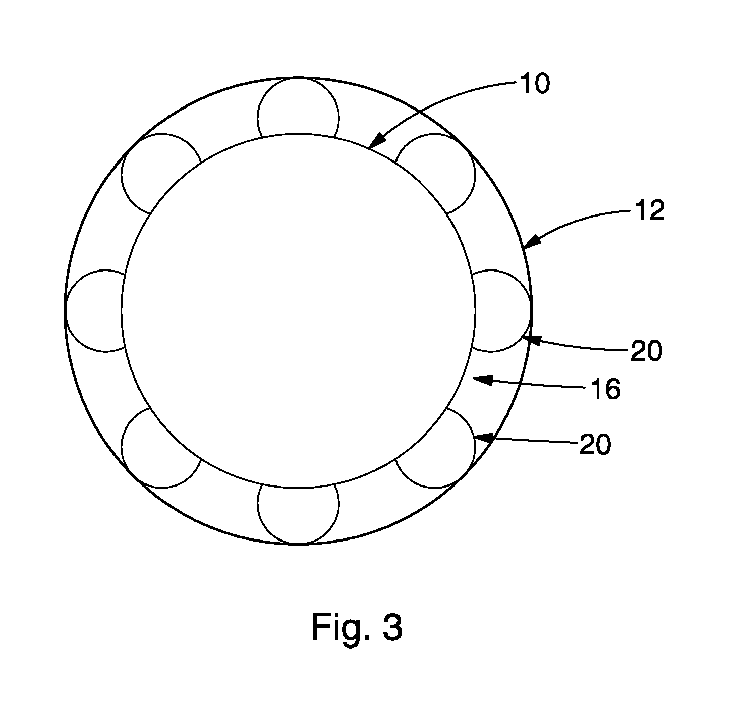
[0045]FIG. 3 shows a third embodiment in which eight radial portions 20 of the tubing 10 are expanded against the surrounding casing 12 in the wellbore so as to cause the tubing 10 to centre within the casing 12. In this embodiment an explosive technique is employed to locally deform the tubing 10 in eight equally spaced radial directions whilst ensuring that the integrity of both the tubing 10 and casing 12 is maintained. The spacing between the expanded portions 20 allows fluids to flow through the annulus 16. Although the explosion will be generated by a wireline tool, once the tubing 10 is suitably expanded the tool will be extracted such that no additional equipment is left down-hole in this embodiment.

[0046]As above, once the tubing 10 is centred, a cleaning procedure may be undertaken (both inside the tubing 10 and outside the tubing 10) and holes formed in the production tubing 10 so that a sealant can be pumped into the annulus 16 to form a fluid-tight plug across a preferr...


PUM


Abstract

A method of centralising tubing (10) in a wellbore comprises either providing one or more expandable elements (14) between a tubing and a surrounding casing (12) located in a wellbore and expanding the expandable elements against the casing so as to cause the tubing to centre within the casing; or expanding one or more portions (20) of a tubing against a surrounding casing located in a wellbore so as to cause the tubing to centre within the casing.

Description

FIELD OF THE INVENTION[0001]The present invention relates to a method of centralising tubing in a wellbore. In particular embodiments, the method comprises centralising tubing in a wellbore prior to installing a permanent fluid-tight barrier around the tubing for well abandonment.BACKGROUND TO THE INVENTION[0002]Traditional plug and abandonment operations require that the entire production tubing and associated cabling is pulled from the wellbore prior to installation of a cement plug.[0003]However, the removal of the tubing is a costly and time-consuming exercise as it requires a drill rig on site. There are also associated safety risks.SUMMARY OF THE INVENTION[0004]The Applicants propose an alternative plug and abandonment technique in which the tubing is left in the well and a plug (usually of cement) is formed around the tubing to completely seal the well.[0005]Rotation and centralisation are two of the most important parameters for a successful cement placement. However, produc...

Claims


Application Information

Patent Timeline
IPC IPC(8): E21B17/10E21B33/13
CPCE21B43/103E21B17/10E21B17/1078E21B17/1014E21B17/1021E21B33/13E21B17/1007E21B43/105
Inventor GRIMSBO, GJERMUNDHEMMINGSEN, PAL VIGGOGODOY, RUNE
Owner DEN NORSKE STATS OLJESELSKAP AS
Why Eureka
Try Eureka