Method of centralising tubing in a wellbore
a wellbore and tubing technology, applied in the direction of wellbore/well accessories, drilling accessories, fluid removal, etc., can solve the problems of ineffective centralisation, increased risk of poor and incomplete cement job, and failure to seal, so as to achieve more corrosive environments, more time-efficient, and effective centralisation of production tubing
- Summary
- Abstract
- Description
- Claims
- Application Information
AI Technical Summary
Benefits of technology
Problems solved by technology
Method used
Image
Examples
first embodiment
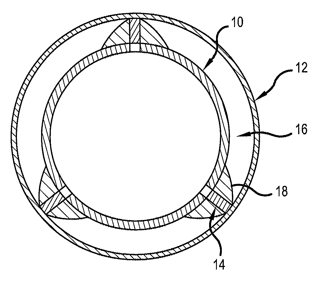
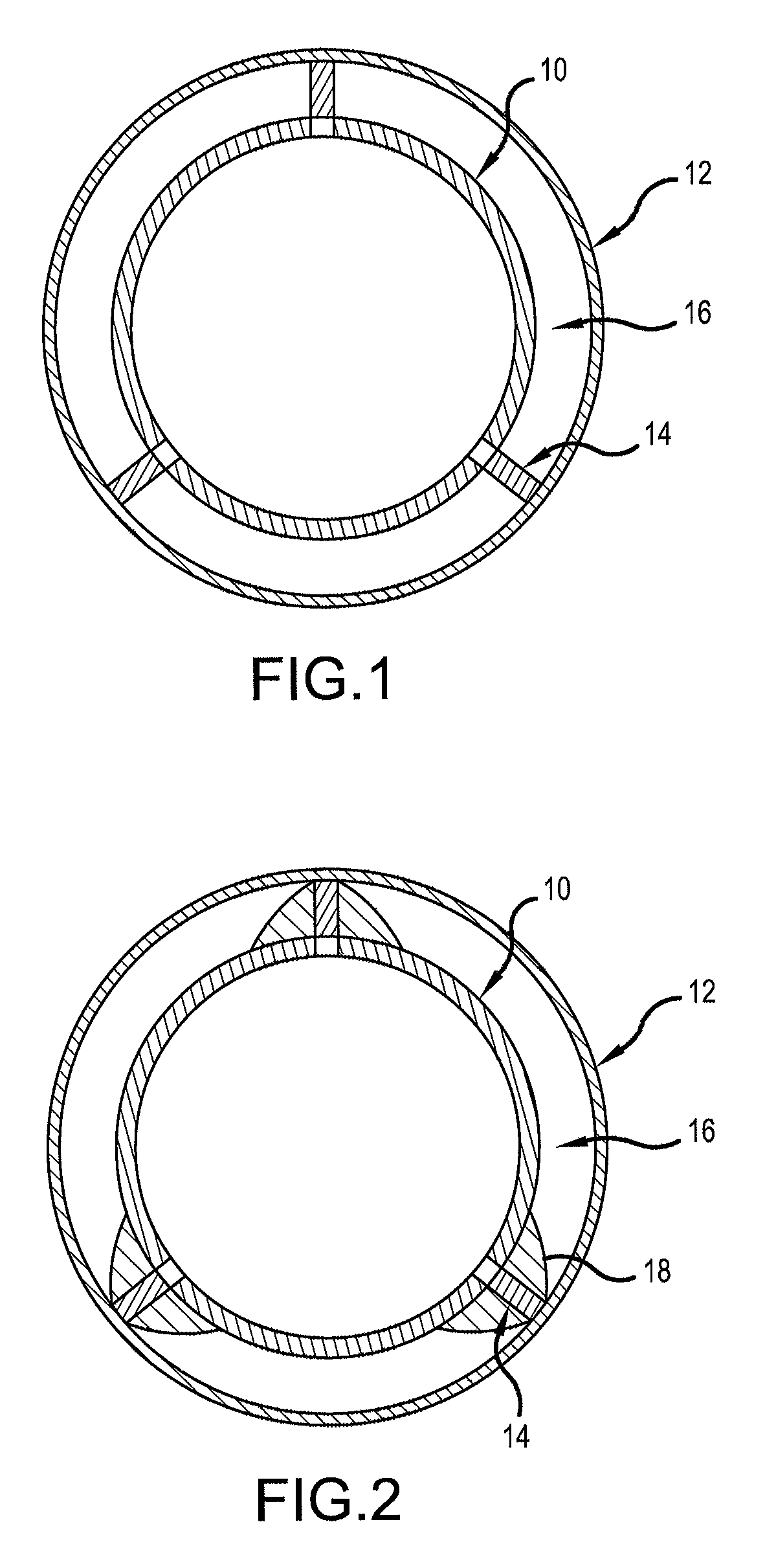
[0040]In accordance with the first embodiment, radial holes are cut in the tubing 10 and the expandable support elements 14 are inserted into the annulus 16 and expanded against the casing 12 to cause the tubing 10 to centralise. In this case, the expandable support elements 14 are configured as mechanical devices that can be operated via wireline.
[0041]Once the tubing 10 is centred, the same holes (or additional holes) may be utilised to flush and clean-out the annulus 16 before a sealant (e.g. cement) is pumped into the annulus 16 to form a plug therein. It will be noted that in this embodiment, the expandable support elements 14 are left in place and the plug is formed around them.
second embodiment
[0042]FIG. 2 shows a second embodiment in which the production tubing 10 is provided with three expandable elements 14 located around the outside of the tubing 10 and retained by an intermediate tubular 18, prior to insertion of the production tubing 10 in the wellbore. The expandable elements 14 in this embodiment are hydraulic pistons which are initially in a collapsed configuration for ease of installation of the production tubing 10 in the casing 12.
[0043]When it is desired to centralise the tubing 10 (e.g. before a plug and abandonment procedure), the expandable elements 14 will be activated using wireline so as to cause the intermediate tubular 18 to be locally expanded against the casing 12.
[0044]Once the tubing 10 is centred, holes may be formed in the production tubing 10 and the intermediate tubular 18 so that a sealant can be pumped into the annulus 16 to form a fluid-tight plug across the entire width of the annulus 16.
third embodiment
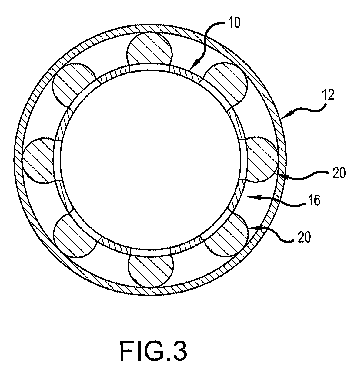
[0045]FIG. 3 shows a third embodiment in which eight radial portions 20 of the tubing 10 are expanded against the surrounding casing 12 in the wellbore so as to cause the tubing 10 to centre within the casing 12. In this embodiment an explosive technique is employed to locally deform the tubing 10 in eight equally spaced radial directions whilst ensuring that the integrity of both the tubing 10 and casing 12 is maintained. The spacing between the expanded portions 20 allows fluids to flow through the annulus 16. Although the explosion will be generated by a wireline tool, once the tubing 10 is suitably expanded the tool will be extracted such that no additional equipment is left down-hole in this embodiment.
[0046]As above, once the tubing 10 is centred, a cleaning procedure may be undertaken (both inside the tubing 10 and outside the tubing 10) and holes formed in the production tubing 10 so that a sealant can be pumped into the annulus 16 to form a fluid-tight plug across a preferr...
PUM
 Abstract
Description
Claims
Application Information
 - R&D
- Intellectual Property
- Life Sciences
- Materials
- Tech Scout
- Unparalleled Data Quality
- Higher Quality Content
- 60% Fewer Hallucinations
Browse by: Latest US Patents, China's latest patents, Technical Efficacy Thesaurus, Application Domain, Technology Topic, Popular Technical Reports.
© 2025 PatSnap. All rights reserved.Legal|Privacy policy|Modern Slavery Act Transparency Statement|Sitemap|About US| Contact US: help@patsnap.com


