Method of acquiring information of hydraulic fracture geometry for evaluating and optimizing well spacing for multi-well pad

a fracture geometry and multi-well technology, applied in the field of reserve technology, can solve the problems of significant reducing the value of resources, affecting the efficiency of drilling, and economic marginality, and achieve the effect of reducing costs and increasing the certainty of results

Active Publication Date: 2016-08-18
STATOIL GULF SERVICES
View PDF7 Cites 23 Cited by
  • Summary
  • Abstract
  • Description
  • Claims
  • Application Information

AI Technical Summary

Benefits of technology

[0008]Accordingly, it is an object of the present invention to provide a method of acquiring information of hydraulic fracture geometry for optimizing well spacing for a multi-well

Problems solved by technology

However, even with these technological enhancements, these resources can be economically marginal and often only recover 5-15% of the original oil in place under primary depletion.
This technique is expensive and time consuming and often gives a highly uncertain answer, requiring this procedure to be repeated many times to increase accuracy in the result.
This procedure, which often ends up with under drilling and over drilling numerous pads, can significantly reduce the value of the resource due to inefficient development.
However, this technology is often questionable for a number of reasons.
A second challenge with microseismic is that it requires knowledge of the subsurface, particularly wave velocities in the media, which are often unknown and have high uncertainty.
Finally, the processing methods themselves are often brought into question, as many service companies who provide this technique use veiled algorithms and openly admit the uncertainty in these processing methods.
However, these approaches are still in the research stage and will likely be quite costly and potentially complex even if they are commercialized.
The shut-in times and data acquisition times for uncon

Method used


Image

  • Method of acquiring information of hydraulic fracture geometry for evaluating and optimizing well spacing for multi-well pad
  • Method of acquiring information of hydraulic fracture geometry for evaluating and optimizing well spacing for multi-well pad
  • Method of acquiring information of hydraulic fracture geometry for evaluating and optimizing well spacing for multi-well pad

Examples


Embodiment Construction

[0016]The present invention will now be described in detail with reference to the accompanying drawings, wherein the same reference numerals will be used to identify the same or similar elements throughout the several views. It should be noted that the drawings should be viewed in the direction of orientation of the reference numerals.

[0017]The present invention is directed to design the stage sequencing of a multi-well hydraulic fracturing job and design a pressure measurement technique during stimulation to acquire data that can be interpreted and analyzed for evaluating hydraulic fracture geometry, connectivity, and proximity and optimizing well spacing.

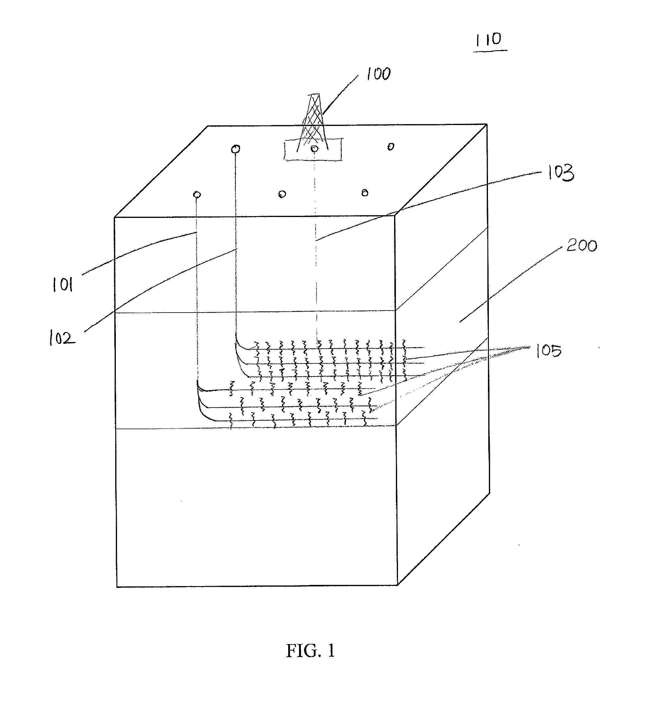
[0018]FIG. 1 shows an exemplary diagram of a drilling operation on a multi-well pad. One of ordinary skill in the art will appreciate that the drilling operation shown in FIG. 1 is provided for exemplary purposes only, and accordingly should not be construed as limiting the scope of the present invention. For example, the number o...


PUM


Abstract

A method for optimizing well spacing for a multi-well pad which includes a first group of wells and a second group of wells is provided. The method includes the steps of: creating a fracture in a stage in a first well in the first group of wells; isolating a next stage in said first well in the first group of wells from said stage; creating a fracture in said next stage in the first well in the first group after the step of isolating; measuring a pressure by using a pressure gauge in direct fluid communication with said next stage in the first well in the first group of wells; creating a fracture in one or more stages in a well in the second group of wells in a manner such that the fracture in the well in the second group of wells induces the pressure measured in the first well to change; and recording the pressure change in the next stage of the first well.

Description

BACKGROUND OF THE INVENTION[0001]1. Field of the Invention[0002]The present invention relates to reservoir technology, and more particularly to a method of acquiring information of hydraulic fracture geometry for evaluating and optimizing well spacing for a multi-well pad.[0003]2. Description of Background Art[0004]Over the years, the research on reservoir technology focuses on maximizing the value of ultra-tight resources, sometimes referred to as shales or unconventionals resources. Ultra-tight resources, such as the Bakken, have very low permeability compared to conventional resources. They are often stimulated using hydraulic fracturing techniques to enhance production and often employ ultra-long horizontal wells to commercialize the resource. However, even with these technological enhancements, these resources can be economically marginal and often only recover 5-15% of the original oil in place under primary depletion. Therefore, optimizing the development of these ultra-tight...

Claims


Application Information

Patent Timeline
IPC IPC(8): E21B43/30E21B47/06E21B33/134E21B43/26
CPCE21B43/17E21B43/26E21B47/06E21B33/134E21B43/30E21B43/126
Inventor DAWSON, MATTHEW A.
Owner STATOIL GULF SERVICES
Why Eureka
Try Eureka