Aerodynamic Modeling Using Flight Data

Active Publication Date: 2016-08-18
NASA
View PDF0 Cites 47 Cited by
  • Summary
  • Abstract
  • Description
  • Claims
  • Application Information

AI Technical Summary

Benefits of technology

[0068]In light of the foregoing background, the following presents a simplified summary of the present disclosure in order to provide a basic understanding of some aspects of the various implementations of this disclosure. This summary is not an extensive overview of the embodiments described herein. It is not intended to identify key or critical elements, or to delineate the scope of the embodiments described in this disclosure. The following summary merely presents some concepts of the embodiments of this disclosure in a simplified form as a prelude to the more detailed description provided below.
[0069]In one aspect, this disclosure relates to a method for modeling of vehicle aerodynamics, including control inputs to the vehicle, which may be an aircraft, receiving sensor data in response to the control inputs, and selecting explanatory variables from the sensor data. The method further includes calculation of membership functions for the explanatory variables, and defining fuzzy cell internal functions to be used to determine a model output is a weighted sum of the internal functions.
[0070]In another aspect, this disclosure includes a non-transitory computer-readable storage medium comprising computer-executable instructions configured to cause the processor to receive data from sen

Problems solved by technology

However, these techniques can be expensive, time-consuming, and have inherent fidelity limitations.
For example, data collected from wind tunnel tests and/or computational fluid dynamics testing may include limitations arising from factors such as, but not limited to, wind-tun

Method used


Image

  • Aerodynamic Modeling Using Flight Data
  • Aerodynamic Modeling Using Flight Data
  • Aerodynamic Modeling Using Flight Data

Examples


Example

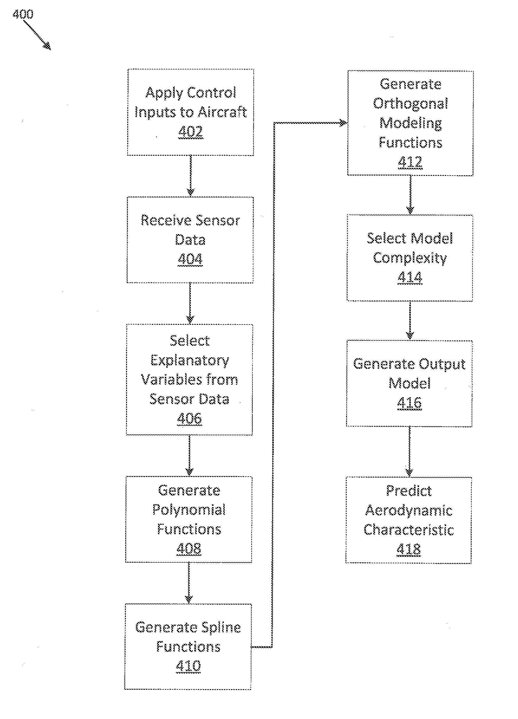
[0079]Development of a global aerodynamic model of a vehicle, such as for example an aircraft, using flight data gathered from a full-scale aircraft may avoid one or more issues of fidelity that may be encountered when using data derived from scaled testing in wind tunnels, or from computational methods. However, conventional full-scale flight testing may be associated with one or more additional limitations. For example, conventional full-scale flight testing may produce inadequate data due to time limitations associated with the high cost of full-scale flight testing. Advantageously, the systems and methods described herein may be utilized to more quickly develop a global aerodynamic model of an aircraft. As such, the systems and methods described herein may be utilized to develop a global aerodynamic model of an aircraft in real-time, during a test flight. Further, the increased speed at which the systems and methods described herein allow for an aerodynamic model to be developed...


PUM


Abstract

Systems and methods are described for development of a nonlinear global aerodynamic model using fuzzy logic modeling as well as multivariate orthogonal function modeling with splines. The systems and methods described herein may be utilized to more quickly develop a global aerodynamic model of an aircraft, allowing for development of a global aerodynamic model of an aircraft in real-time, during a test flight, and reducing time and cost associated with the model development.

Description

CROSS-REFERENCE TO RELATED PATENT APPLICATION(S)[0001]This patent application claims the benefit of and priority to U.S. Provisional Patent Application Ser. No. 61 / 909,467, filed on Nov. 27, 2013, the contents of which are hereby incorporated by reference in their entirety.STATEMENT REGARDING FEDERALLY SPONSORED RESEARCH OR DEVELOPMENT[0002]This invention described herein was made by employees of the United States Government and may be manufactured and used by or for the Government of the United States for governmental purposes without the payment of any royalties thereon or therefore.TECHNICAL FIELD OF THE INVENTION[0003]Aspects of this disclosure generally relate to systems and methods for modeling of aerodynamic performance of a vehicle, which may include but is not limited to an aircraft.BACKGROUND OF THE INVENTION[0004]A global aerodynamic model may describe, as one or more mathematical formulae, the aerodynamic behavior of a vehicle, such as, among others, an airplane or helic...

Claims


Application Information

Patent Timeline
IPC IPC(8): G01M9/08G06N7/02G06F17/11
CPCG01M9/08G06N7/02G06F17/11G06F30/15G06F30/20G06F2111/10Y02T90/00
Inventor BRANDON, JAYMORELLI, EUGENE A.
Owner NASA
Why Eureka
Try Eureka