
Frame based package for flip-chip LED

Active Publication Date: 2016-08-18
LUMILEDS
View PDF3 Cites 4 Cited by
  • Summary
  • Abstract
  • Description
  • Claims
  • Application Information

AI Technical Summary

Benefits of technology

The patent text describes a new way to create a light emitting module that is easy to handle and has contacts on the sides that allow for connections. The design should be small and compact. The technical effect of this invention is to simplify the process of creating a light emitting module and make it more user-friendly.

Problems solved by technology

This substantial volume and footprint ‘overhead’ limits the use of such a light emitting module in applications such as flash or illumination elements for portable devices, such as smart phones and the like.

Method used


Image

  • Frame based package for flip-chip LED
  • Frame based package for flip-chip LED
  • Frame based package for flip-chip LED

Examples


Embodiment Construction

[0021]In the following description, for purposes of explanation rather than limitation, specific details are set forth such as the particular architecture, interfaces, techniques, etc., in order to provide a thorough understanding of the concepts of the invention. However, it will be apparent to those skilled in the art that the present invention may be practiced in other embodiments, which depart from these specific details. In like manner, the text of this description is directed to the example embodiments as illustrated in the Figures, and is not intended to limit the claimed invention beyond the limits expressly included in the claims. For purposes of simplicity and clarity, detailed descriptions of well-known devices, circuits, and methods are omitted so as not to obscure the description of the present invention with unnecessary detail.

[0022]Thick, self-supporting light emitting devices are now commonly available. FIGS. 8A-8C illustrate an example of several self-supporting lig...


PUM


Abstract

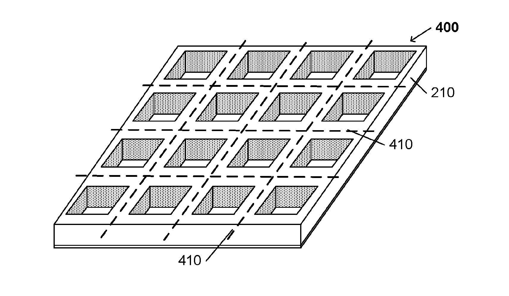
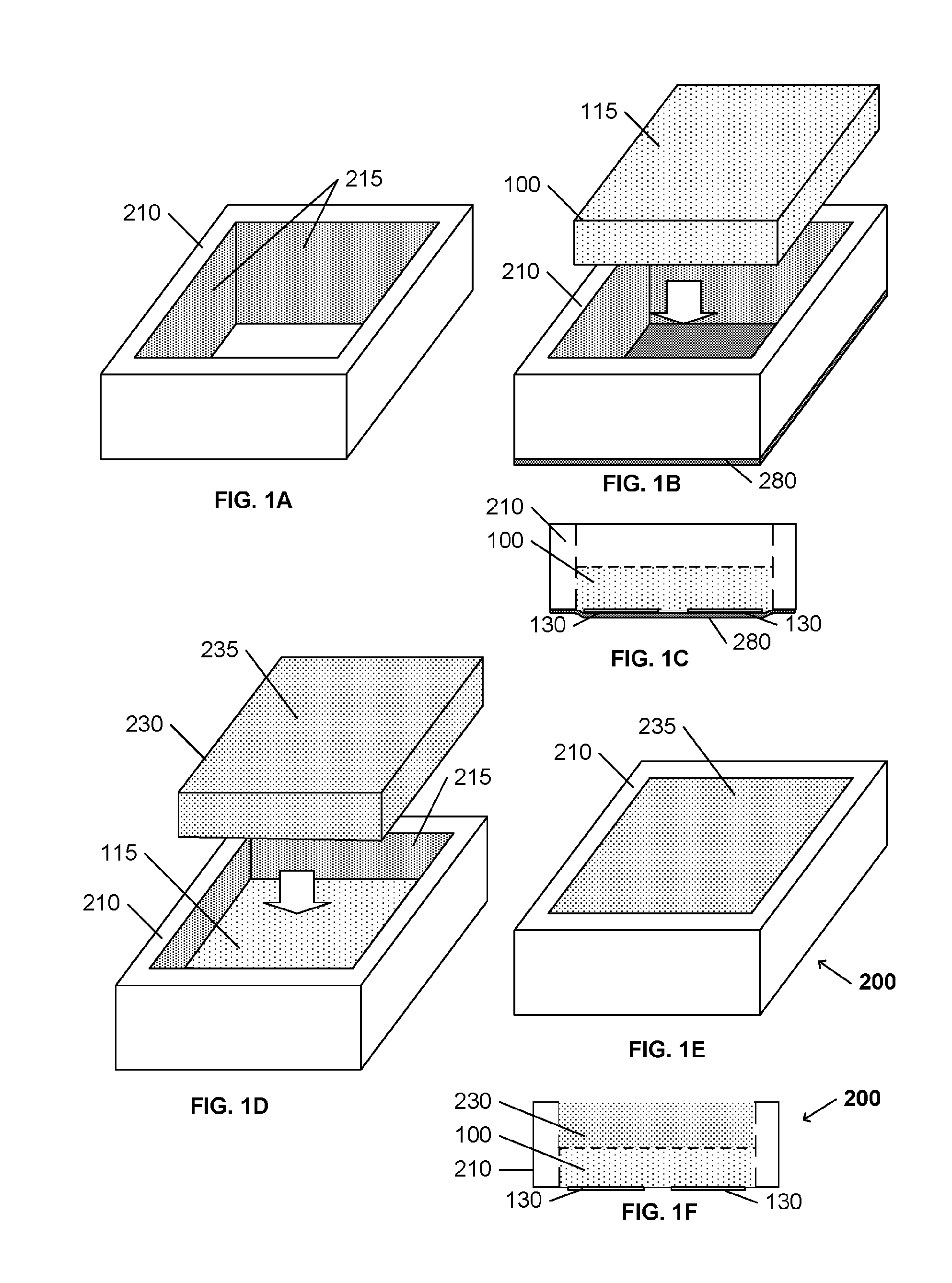
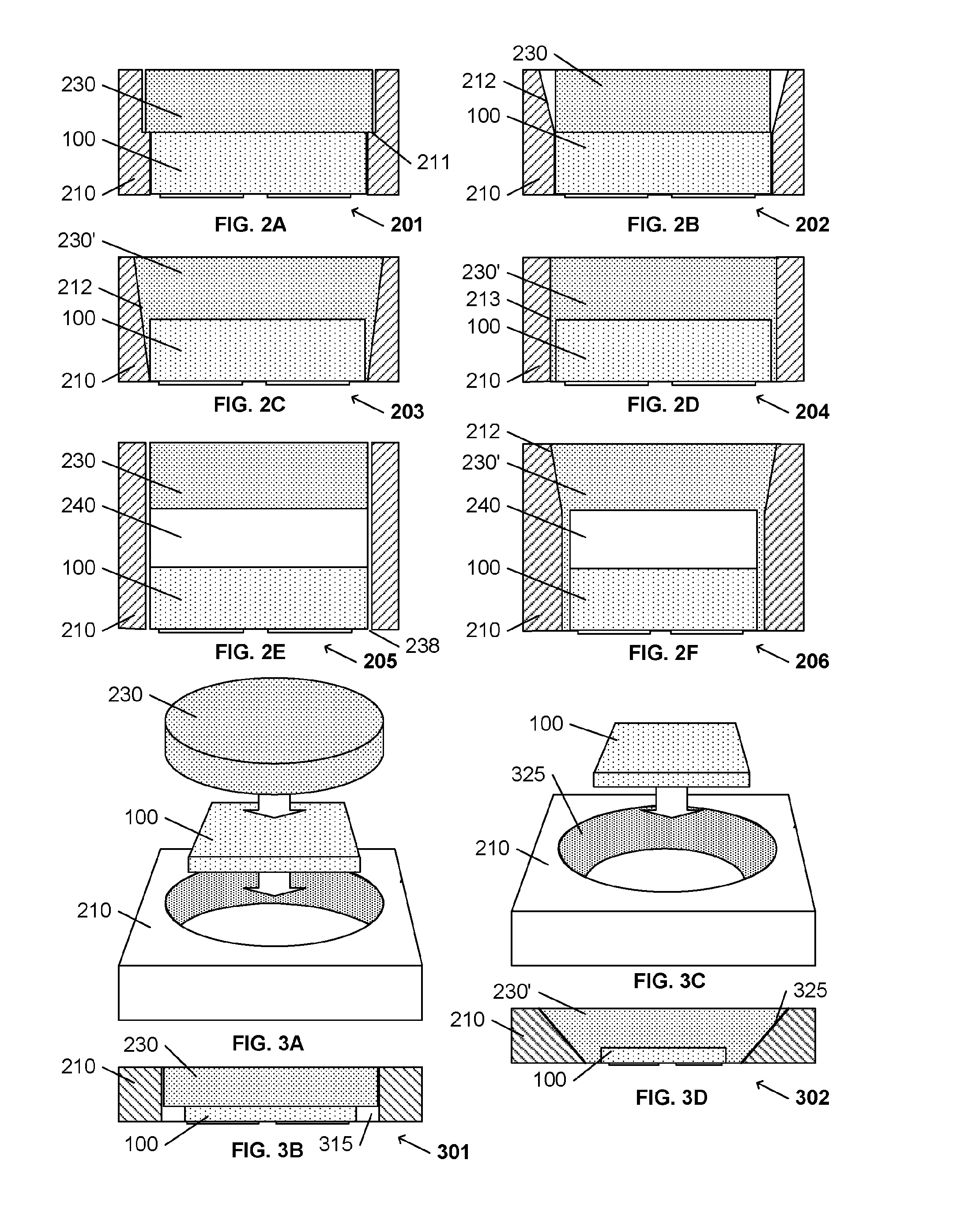
A hollow frame is configured to surround the periphery of a substantially self-supporting flip-chip light emitting device. The frame may be shaped to also contain a wavelength conversion element above the light emitting surface of the light emitting device. The lower surface of the light emitting device, which is exposed through the hollow frame, includes contact pads coupled to the light emitting element for surface mounting the light emitting module on a printed circuit board or other fixture. The flip-chip light emitting device may include a patterned sapphire substrate (PSS) upon which the light emitting element is grown, the patterned surface providing enhanced light extraction from the light emitting element, through the patterned sapphire substrate.

Description

FIELD OF THE INVENTION[0001]This invention relates to the field of light emitting devices, and in particular to a frame that provides a reflective enclosure about the periphery of the device.BACKGROUND OF THE INVENTION[0002]The ever expanding use of semiconductor light emitting devices has produced a highly competitive market for these devices. In this market, performance and price are often significant for providing product distinction among vendors. Accordingly, a common objective is to reduce the cost of production while providing equivalent or better performance from the light emitting device.[0003]One technique for providing relatively inexpensive packaging of a light emitting element is to place the light emitting element in a frame with leadframe contacts that facilitate external connections to the light emitting element. An LED leadframe generally comprises a pair of conductors that are shaped to provide for external connections to the LED. A support frame may be molded abou...

Claims


Application Information

Patent Timeline
IPC IPC(8): H01L33/60H01L33/50H01L33/48H01L33/00H01L33/62
CPCH01L33/0095H01L33/486H01L33/50H01L33/58H01L33/60H01L33/62H01L2933/0041H01L2933/0058H01L33/502H01L33/0075H01L2933/0033H01L25/0753H01L33/483H01L2924/12041
Inventor STOCKMAN, STEPHEN ANDREWDE SAMBER, MARC ANDRESHCHEKIN, OLEG BORISOVICHSWEEGERS, NORBERTUS ANTONIUS MARIAHAQUE, ASHIM SHATILMARTYNOV, YOURII
Owner LUMILEDS
Learn More