Light emitting device

a technology of light-emitting devices and light-emitting components, which is applied in the direction of semiconductor devices, basic electric elements, electrical appliances, etc., can solve the problems of significant reduction in thermal resistance and deterioration of reliability of light-emitting devices, and achieve the effect of minimizing the occurrence of voids during soldering

Active Publication Date: 2016-08-18
SEOUL VIOSYS CO LTD
View PDF1 Cites 33 Cited by
  • Summary
  • Abstract
  • Description
  • Claims
  • Application Information

AI Technical Summary

Benefits of technology

[0014]The invention meets the aforementioned need in light emitting devices by providing a bonding pad or similar structure, which is soldered or heat fused...

Problems solved by technology

In addition, although a high output light emitting device typically generates large amounts of heat upon application of high injection current, distance from an active layer corresponding to a heat generation region to a heat dissipation structure in the light emitting device is short, thereby enabling easy heat dissipation and significant reduction in thermal resistance.
In the r...

Method used


Image

  • Light emitting device
  • Light emitting device
  • Light emitting device

Examples


Embodiment Construction

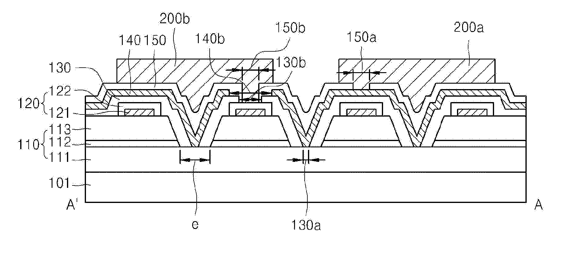
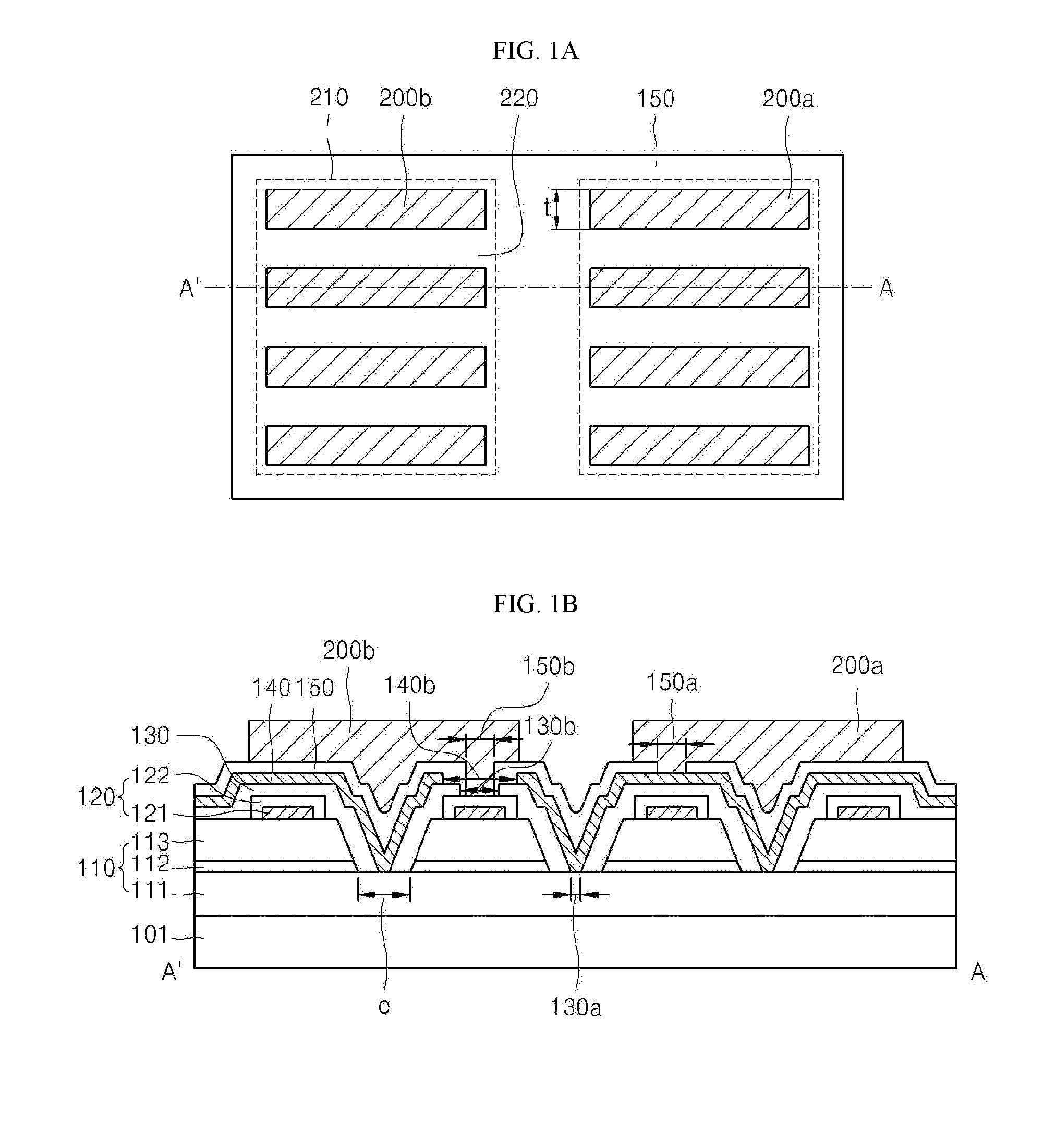
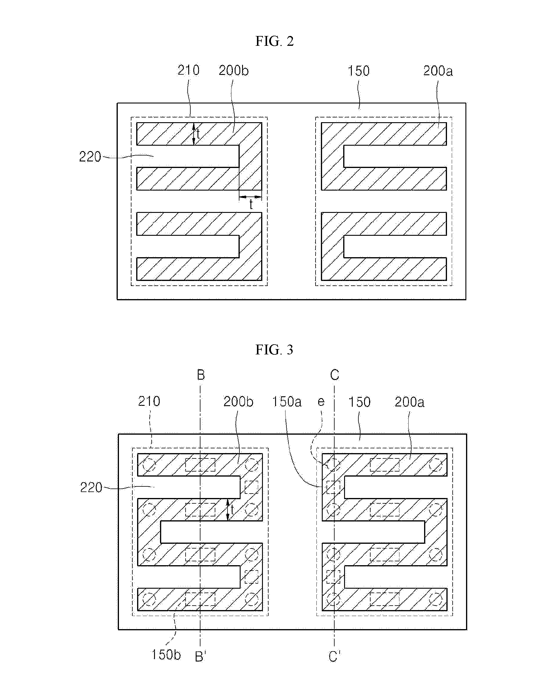
[0060]In the following description, for the purposes of explanation, numerous specific details are set forth in order to provide a thorough understanding of various exemplary embodiments. It is apparent, however, that various exemplary embodiments may be practiced without these specific details or with one or more equivalent arrangements. In other instances, well-known structures and devices are shown in block diagram form in order to avoid unnecessarily obscuring various exemplary embodiments.

[0061]Unless otherwise specified, the illustrated exemplary embodiments are to be understood as providing exemplary features of varying detail of various exemplary embodiments. Therefore, unless otherwise specified, the features, components, modules, layers, films, panels, regions, and / or aspects of the various illustrations may be otherwise combined, separated, interchanged, and / or rearranged without departing from the disclosed exemplary embodiments. Further, in the accompanying figures, the...


PUM


Abstract

A light emitting device in which a bonding pad is soldered to a mounting substrate, wherein the bonding pad may be formed in various shapes that can minimize the occurrence of voids during soldering or heat fusion.

Description

CROSS-REFERENCE TO RELATED APPLICATIONS[0001]This application is a Continuation-in-part of International Patent Application No. PCT / KR2015 / 008841, filed on Aug. 24, 2015, and claims priority from and the benefit of Korean Patent Application No. 10-2014-0113470, filed on Aug. 28, 2014, Korean Patent Application No. 10-2014-0194260, filed on Dec. 30, 2014, and Korean Patent Application No. 10-2015-0116740, filed on Aug. 18, 2015, each of which is incorporated by reference for all purposes as if fully set forth herein.BACKGROUND[0002]1. Field[0003]Exemplary embodiments of the invention relate to a light emitting device, and, more particularly, to a light emitting device including a bonding pad soldered to a mounting substrate and having a particular structure capable of minimizing occurrence of voids during soldering.[0004]2. Discussion of the Background[0005]A high output light emitting device can be obtained by taking into account various design factors such as improvement in luminou...

Claims


Application Information

Patent Timeline
IPC IPC(8): H01L33/62H01L33/24H01L33/38H01L33/06H01L33/36H01L33/32
CPCH01L33/62H01L33/36H01L33/24H01L33/382H01L33/06H01L33/32H01L33/08H01L33/38
Inventor CHAE, JONG HYEONLEE, SO RAYE, KYUNG HEE
Owner SEOUL VIOSYS CO LTD
Why Eureka
Try Eureka