Pneumatic tire
Active Publication Date: 2016-08-25
SUMITOMO RUBBER IND LTD
View PDF3 Cites 11 Cited by
- Summary
- Abstract
- Description
- Claims
- Application Information
AI Technical Summary
Benefits of technology
The present invention aims to improve the performance of tires in preventing separation from rim and reducing fastening force gradient of bead. By shaping the bead and arranging the cross-sections of wire in the core, the inventors found that the bead can better fit the rim and be securely fastened. This allows for easy fitting and prevents rim slip and separation, even if the rim has a deviation from standard value. The pneumatic tire of the present invention achieves improved performance and ease of fitting.
Problems solved by technology
This leads to decrease in steering stability.
Further, rim slip may cause mass balance of the tire to be reduced.
This leads to vibration of the vehicle during traveling.
Moreover, the insufficient fastening force of the bead may cause separation of the bead from the rim when the vehicle turns, and this may cause “separation from rim”.
However, if the bead has great fastening force, it is necessary to exert a high fitting pressure in order to fit the beads onto the rim.
Time and effort are required to mount such a tire onto the rim.
The twisting may lead to imperfect fitting.
Method used
View moreImage
Smart ImageViewing Examples

Examples
example 1
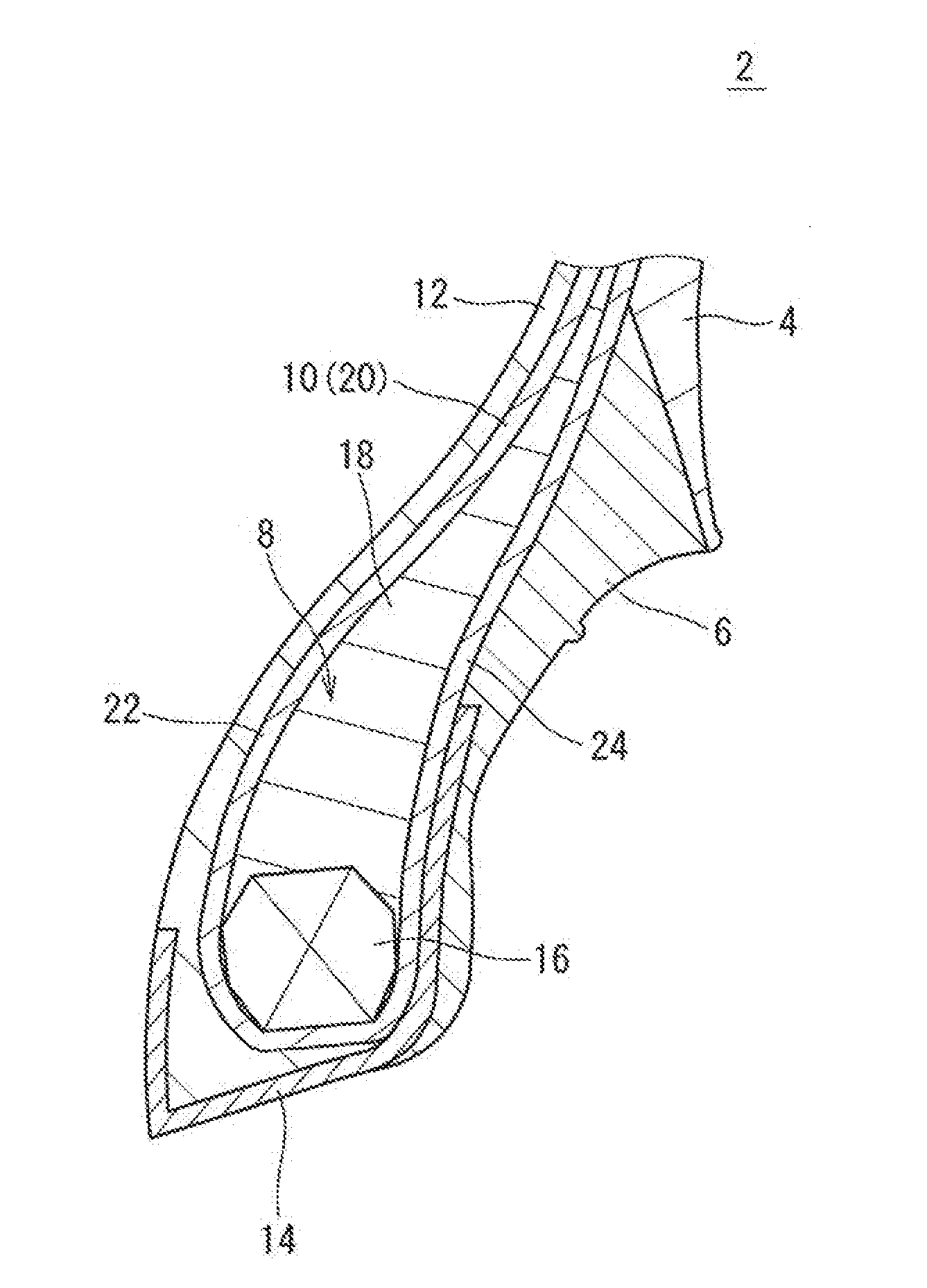
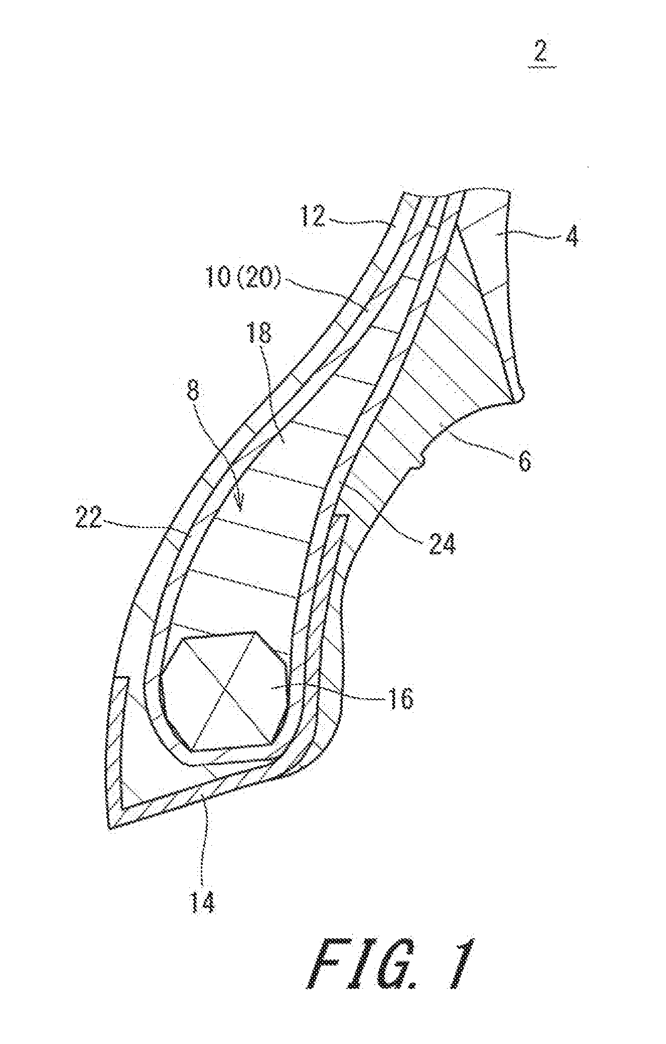
[0066]A tire of example 1 having the configuration shown in FIG. 1 and the specifications indicated below in Table 1 was obtained. This tire had a size of 205 / 40R16. This tire had the core structure shown in FIG. 2. This is indicated as “FIG. 2” in the cell of the core structure in Table 1. The angle between the bottom side of the core and the bead base line BBL was 5°. This is indicated in the cell of the core angle α in Table 1.
example 2
[0070]A tire of example 2 was obtained in the same manner as for example 1 except that the core structure was as shown in (A) of FIG. 3.
example 3
[0071]A tire of example 3 was obtained in the same manner as for example 1 except that the core structure was as shown in (B) of FIG. 3.
Login to View More PUM
 Abstract
[Object] A pneumatic tire 2 that allows prevention of rim slip and separation from rim and that can be easily fitted, is provided.[Solution] In the tire 2, in a cross-section of a core 16 of a bead 8 taken at a plane perpendicular to the circumferential direction, two or more rows of wire cross-sections 26 aligned almost in the axial direction are stacked. When, of the rows, the radially innermost row is a first row, and a row immediately outside the innermost row in the radial direction is a second row, the number of the cross-sections 26 of the wire in the first row is less than the number of the cross-sections 26 of the wire in the second row. An inner end E2 of the second row is located axially inward of a line that is drawn from an inner end E1 of the first row and that is perpendicular to a direction in which the first row extends. In the cross-section of the core 16 oaken at a plane perpendicular to the circumferential direction, an angle between a bottom side of the core 16 and a bead base line BBL is greater than or equal to 2°, and not greater than 9°.
Description
TECHNICAL FIELD[0001]The present invention relates to pneumatic tires.BACKGROUND ART[0002]A vehicle wheel includes a tire and a rim. The tire is mounted on the rim by the beads of the tire fitting onto the rim. Close contact between the beads and the rim allows hermetic seal. The fitting of the beads onto the rim is very significant for the wheel.[0003]The rim is fastened by the beads fitted on the rim. The tire is fixed to the rim by the fastening force. When a vehicle is quickly accelerated or decelerated, a great force is generated in the circumferential direction between the rim and the bead. If the fastening force of the bead is insufficient, the rim may slip on the bead, which is called “rim slip.” If rim slip occurs, the transmission of a force from the vehicle body to the road surface or from the road surface to the vehicle body is inhibited. This leads to decrease in steering stability. Further, rim slip may cause mass balance of the tire to be reduced. This leads to vibrat...
Claims
Login to View More Application Information
Patent Timeline
 IPC IPC(8): B60C15/04B60C15/02B60C9/02B60C11/00B60C13/00
CPCB60C15/04B60C2200/06B60C2015/0614B60C15/02B60C9/02B60C11/00B60C13/00B60C15/024B60C2015/061B60C2015/046B60C2015/048
Inventor TATSUMI, HIROYUKI
Owner SUMITOMO RUBBER IND LTD