Ultrasound diagnostic device and control method for the same

Active Publication Date: 2016-08-25
KONICA MINOLTA INC
View PDF0 Cites 7 Cited by
  • Summary
  • Abstract
  • Description
  • Claims
  • Application Information

AI Technical Summary

Benefits of technology

[0010]In view of such technical problems, the present disclosure provides an ultrasound diagnostic device and a control method for t

Problems solved by technology

When ultrasound velocity in the examination target part differs from the standard ultrasound velocity in such a manner, a difference in phase may still be present between receive si

Method used


Image

  • Ultrasound diagnostic device and control method for the same
  • Ultrasound diagnostic device and control method for the same
  • Ultrasound diagnostic device and control method for the same

Examples


embodiment

[0041]The following describes an ultrasound diagnostic device 100 pertaining to the embodiment, with reference to the accompanying drawings.

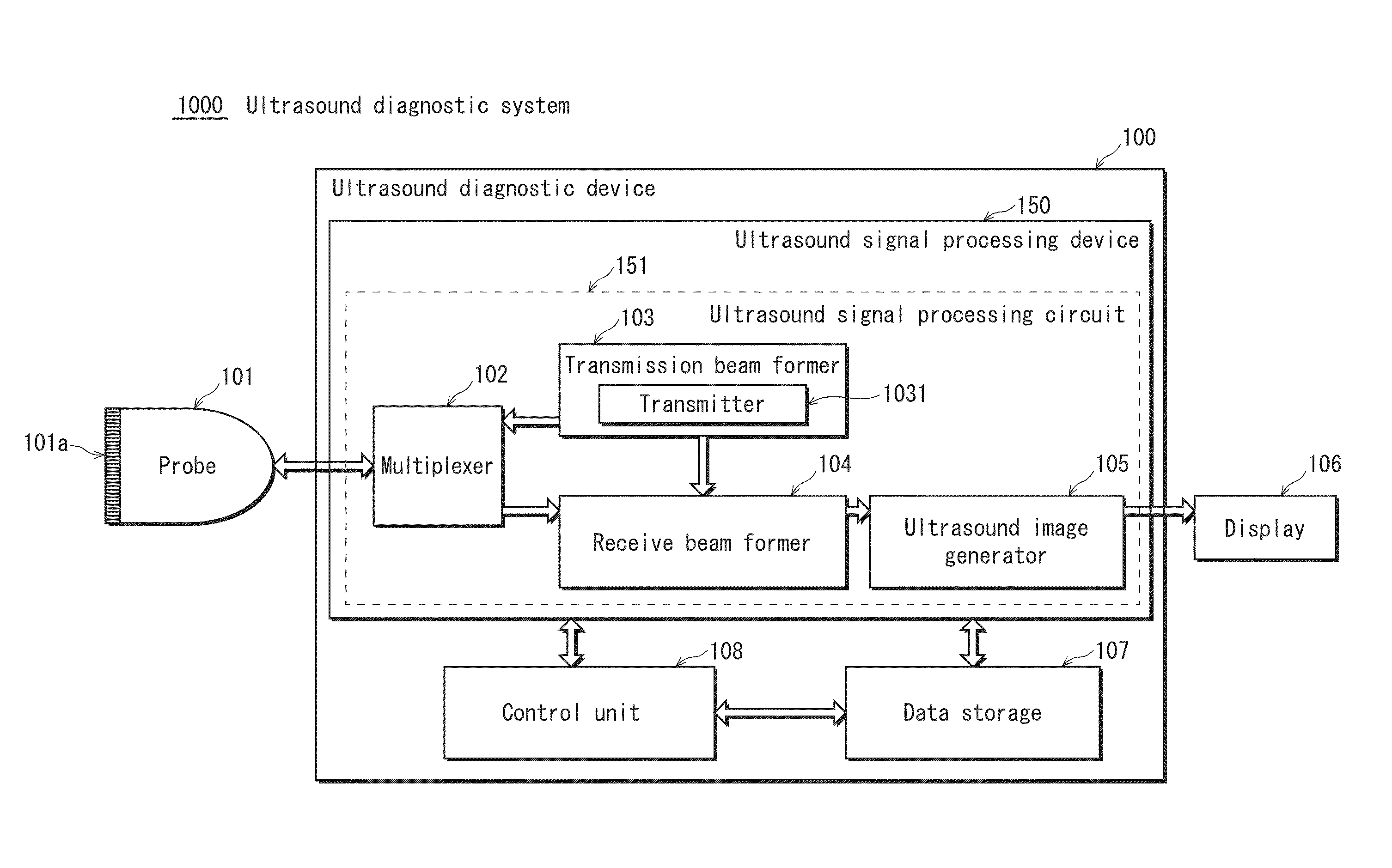
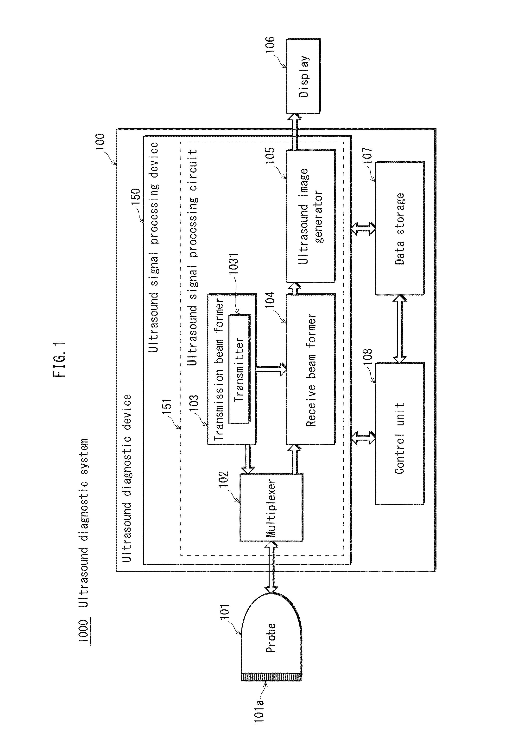
[0042]FIG. 1 illustrates functional blocks of an ultrasound diagnostic system 1000 pertaining to the embodiment. As illustrated in FIG. 1, the ultrasound diagnostic system 1000 includes: a probe 101; the ultrasound diagnostic device 100; and a display unit 106. The probe 101 includes a plurality of transducer elements 101a. The transducer elements 101a are disposed at a surface of a tip portion of the probe 101. Each of the transducer elements 101a transmits ultrasound towards the subject and receives reflected ultrasound (echo signals). The ultrasound diagnostic device 100 causes the probe 101 to perform transmission / reception of ultrasound, and generates an ultrasound image based on signals output from the probe 101. The display unit 106 displays the ultrasound image on any display device provided thereto. The probe 101 and the display unit 10...


PUM


Abstract

An ultrasound diagnostic device to which an ultrasound probe having a plurality of transducer elements is connectable. The ultrasound diagnostic device includes ultrasound signal processing circuitry operating as: a delay-and-sum processor; a determiner; and a velocity value calculator. The determiner determines whether adjustment of a velocity value for a partial area in a subject is necessary, based on acoustic line signal intensities for a specific measurement point in the partial area and other measurement points in the partial area. The specific measurement point is selected from among measurement points in the partial area based on acoustic line signals for the measurement points in the partial area. The velocity value calculator, when the determiner determines that velocity value adjustment is necessary, calculates an adjusted velocity value for the partial area by using the acoustic line signal for the specific measurement point.

Description

[0001]This application is based on an application No. 2015-35710 filed in Japan, the contents of which are hereby incorporated by reference.BACKGROUND OF THE INVENTION[0002](1) Field of the Invention[0003]The present disclosure relates to an ultrasound diagnostic device and a control method for the same. In particular, the present disclosure is related to receive beam forming in an ultrasound diagnostic device.[0004](2) Description of the Related Art[0005]Typically, an ultrasound diagnostic device transmits ultrasound towards the inside of a subject via an ultrasound probe (referred to in the following as a “probe”), and receives reflected ultrasound (an echo) via the probe. The reflected ultrasound is generated within the subject due to tissues in the subject having different acoustic impedances. Further, an ultrasound diagnostic device generates an ultrasound tomographic image based on electric signals acquired through the reception of the reflected ultrasound, and displays the ul...

Claims


Application Information

Patent Timeline
IPC IPC(8): G01S7/52G01S15/89A61B8/00
CPCG01S7/52036G01S15/8906A61B8/4483G01S7/52049G01S15/8997G01S15/8927
Inventor WATANABE, YASUHITO
Owner KONICA MINOLTA INC
Why Eureka
Try Eureka