
Radio communication apparatus, radio communication method, communication control apparatus, and communication control method

a radio communication and control apparatus technology, applied in connection management, climate sustainability, high-level techniques, etc., can solve problems such as the risk of local degradation of data rates

Active Publication Date: 2016-08-25
SONY CORP
View PDF7 Cites 12 Cited by
  • Summary
  • Abstract
  • Description
  • Claims
  • Application Information

AI Technical Summary

Benefits of technology

The patent text describes a technique that allows a small cell base station to detect nearby devices and offer them the opportunity to connect to another device when the small cell base station is in a standby state. This improves the user experience and enables smoother handovers.

Problems solved by technology

However, because development of a cellular communication system does not catch up with increase of traffic, there still remains a risk of local degradation of a data rate due to increase of system load and occurrence of a network failure.
However, when the number of small cells operating within a service area of a macro cell increases, radio signals from more near cells act on a radio signal of one cell as interference.

Method used


Image

  • Radio communication apparatus, radio communication method, communication control apparatus, and communication control method
  • Radio communication apparatus, radio communication method, communication control apparatus, and communication control method
  • Radio communication apparatus, radio communication method, communication control apparatus, and communication control method

Examples


first embodiment

2. FIRST EMBODIMENT

2-1. Configuration Example of Small Cell Base Station

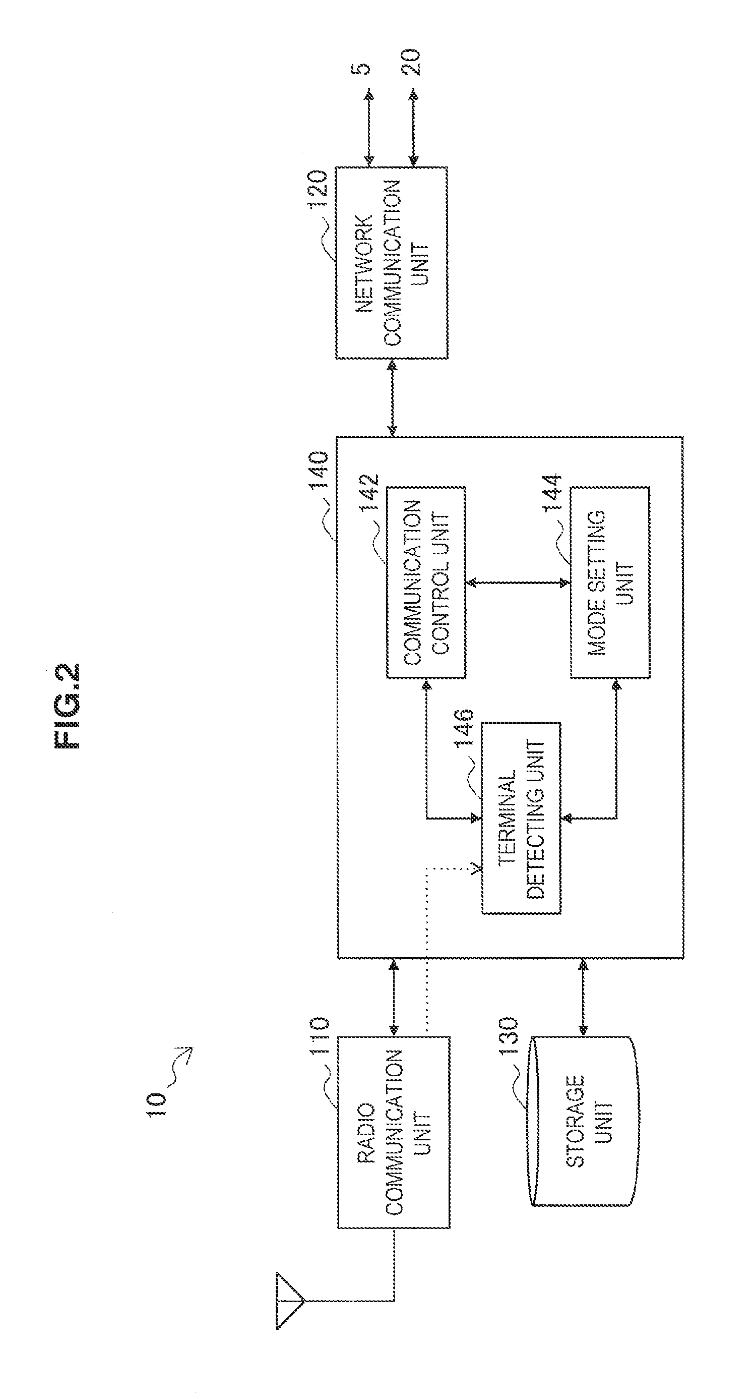
[0065]FIG. 2 is a block diagram illustrating one example of a configuration of a small cell base station 10 according to a first embodiment. Referring to FIG. 2, the small cell base station 10 includes a radio communication unit 110, a network communication unit 120, a storage unit 130 and a control unit 140.

(1) Radio Communication Unit

[0066]The radio communication unit 110 provides radio communication service to one or more terminal apparatuses 30 located within the small cell 18 which overlaps with the macro cell 28. For example, the radio communication unit 110 transmits a reference signal on a downlink channel in the active mode. By receiving this reference signal, the terminal apparatus 30 can be connected to the small cell 18. The terminal apparatus 30 derives communication quality of the small cell 18 by executing measurement for the reference signal transmitted from the radio communication unit 110.

(2) N...

second embodiment

3. SECOND EMBODIMENT

[0113]The above-described Patent Literature 1 proposes a scenario of clustering a plurality of small cells disposed at high density, so that small cells within the cluster operate cooperatively with each other. Therefore, in this section, an embodiment in a case where the small cell base station 10 belongs to such a cluster will be described.

3-1. Outline of System

[0114]FIG. 9 is an explanatory diagram for explaining outline of a radio communication system according to a second embodiment. Referring to FIG. 9, the radio communication system 3 includes small cell base stations 10b, 10c, 10d and 10e, a macro cell base station 20, and terminal apparatuses 30b, 30c and 30z. It should be noted that the number of macro cell base stations, the number of small cell base stations and the number of terminal apparatuses included in the radio communication system 3 are not limited to the example in FIG. 9.

[0115]The small cell base stations 10c, 10d and 10e are small cell base...

application example

4. APPLICATION EXAMPLE

[0146]The technique according to the present disclosure can be applied to various products. For example, a management server having a management function of cell data may be implemented as an upper node of the macro cell base station 20 in a form of a tower server, a lack server, a blade server, or the like. Further, the management function of the cell data may be implemented in a control module mounted on the management server (for example, an integrated circuit module configured with one die, or a card or a blade inserted into a slot of the blade server).

[0147]For example, the small cell base station 10 and the macro cell base station 20 may be realized as any type of evolved Node B (eNB). A small eNB may be an eNB that covers a cell smaller than a macro cell, such as a pico eNB, micro eNB, or home (femto) eNB. Instead, the small cell base station 10 and the macro cell base station 20 may be realized as any other types of base stations such as a NodeB and a b...


PUM


Abstract

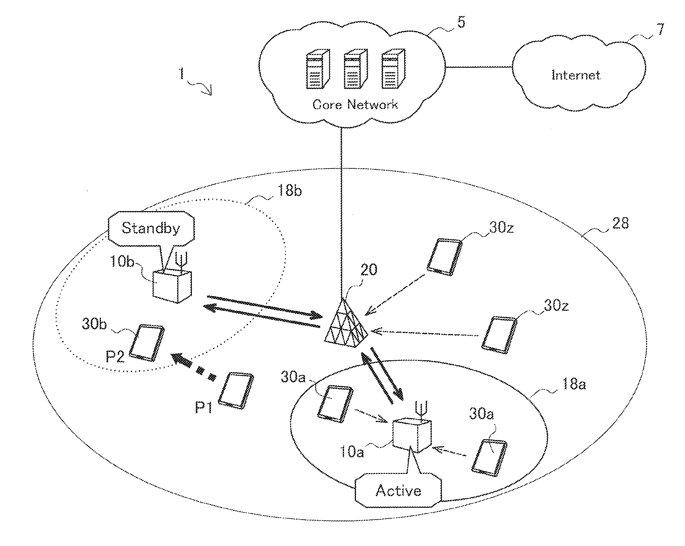
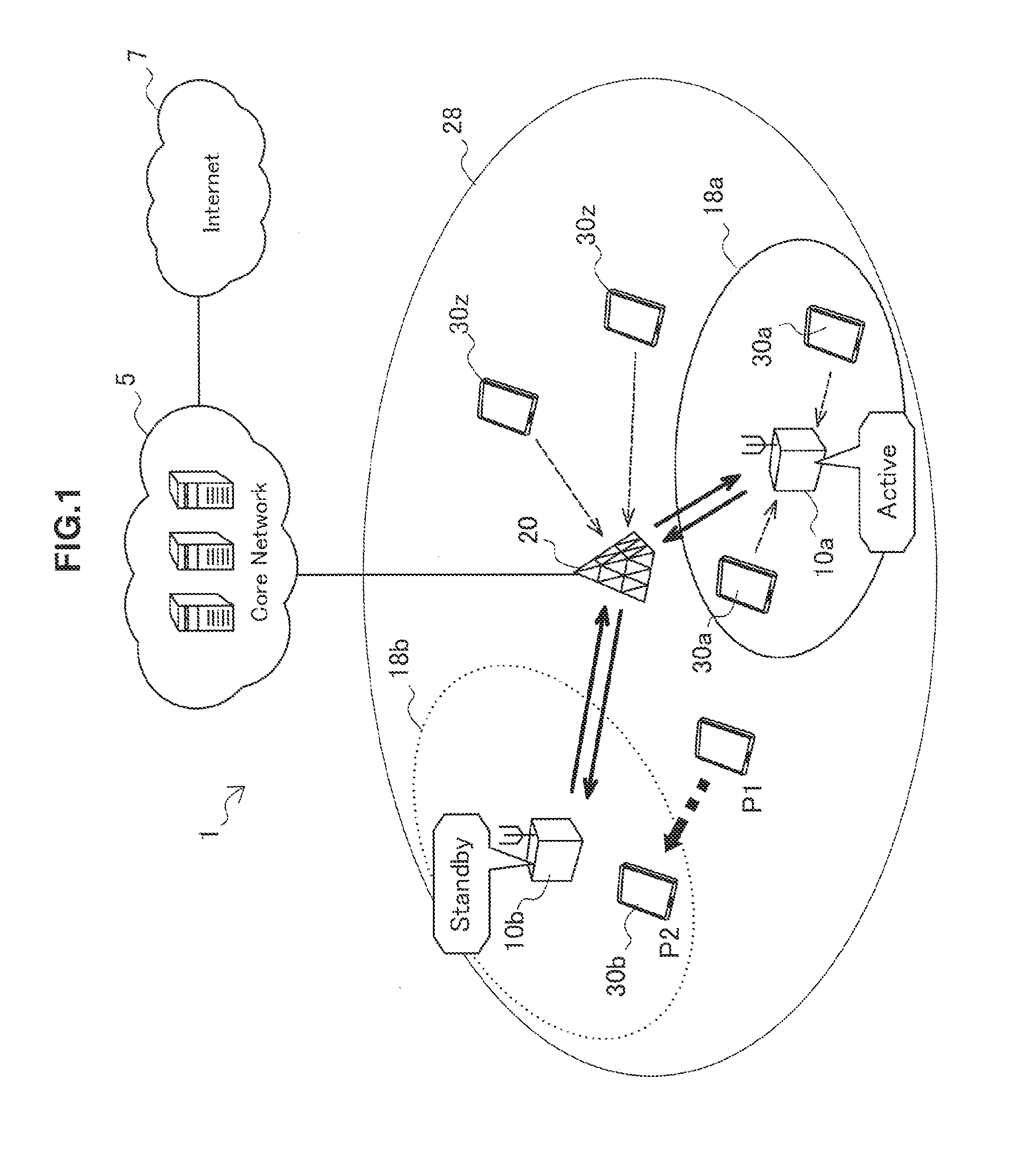
[Object] To be able to detect a terminal in the vicinity of a small cell base station and appropriately provide an opportunity for handover even when the small cell base station is put into a standby state.[Solution] Provided is a radio communication apparatus including: a radio communication unit configured to provide radio communication service to one or more terminals within a second cell which overlaps with a first cell; a detecting unit configured to detect a terminal existing in the vicinity by monitoring strength of an uplink signal transmitted in the first cell while an operation mode of the radio communication unit is set at a standby mode; and a mode setting unit configured to switch the operation mode of the radio communication unit to an active mode when the detecting unit detects the terminal existing in the vicinity.

Description

TECHNICAL FIELD[0001]The present disclosure relates to a radio communication apparatus, a radio communication method, a communication control apparatus, and a communication control method.BACKGROUND ART[0002]A traffic amount handled in radio communication service has increased rapidly in recent years. A user now can download large scale data such as music data and video streaming data from a network on a radio channel. Capacity of a cellular communication system has been improved to achieve a peak data rate of 100 Mbps or higher in downlink by introduction of long term evolution (LTE) which is positioned as 3.9th generation. In the fourth generation mobile phone service which is scheduled to be in practical use around 2015, it is expected that a data rate of 1 Gbps at a maximum in a semi-fixed environment and 100 Mbps at a maximum in a mobile environment can be achieved. However, because development of a cellular communication system does not catch up with increase of traffic, there...

Claims


Application Information

Patent Timeline
IPC IPC(8): H04W36/30H04W72/04H04W36/08H04W16/32H04W84/10H04W52/02
CPCH04W16/32H04W84/10H04W52/0206H04W88/08H04W36/08H04W36/30H04W72/0413H04W36/00H04W52/0251Y02D30/70H04W36/0079H04W76/27H04W72/21
Inventor USUI, TAKASHIKIMURA, RYOTAFURUICHI, SHO
Owner SONY CORP
Learn More