Dental Implant

Inactive Publication Date: 2016-09-01
ZANNA MASSIMO
View PDF9 Cites 7 Cited by
  • Summary
  • Abstract
  • Description
  • Claims
  • Application Information

AI Technical Summary

Benefits of technology

[0010]Therefore, an object of the present invention is to provide a dental implant which is reliable, in other words having a high retainability,

Problems solved by technology

The osteointegration ensured by this kind of solution is not satisfying because it does not

Method used


Image

  • Dental Implant
  • Dental Implant
  • Dental Implant

Examples


Example

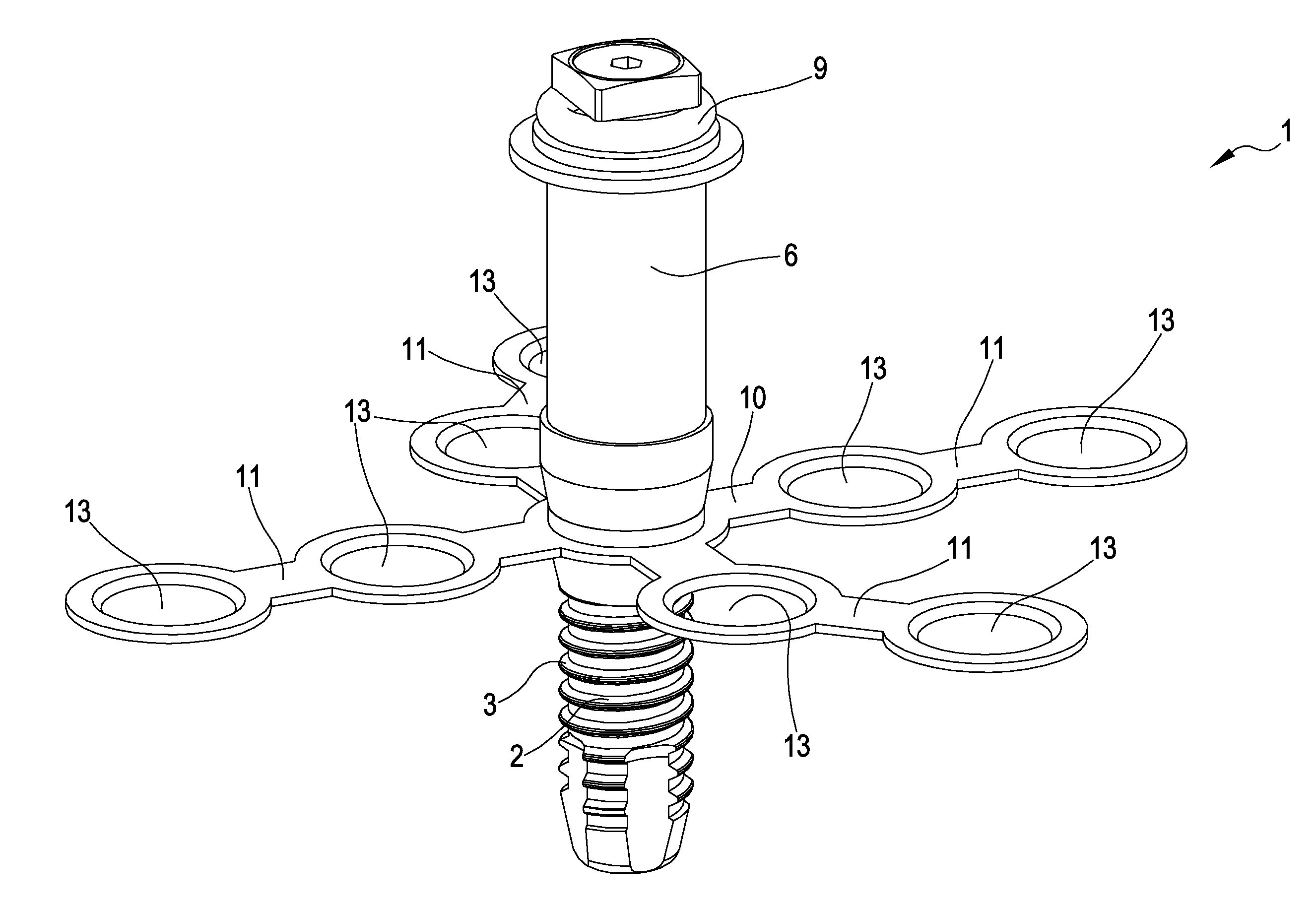
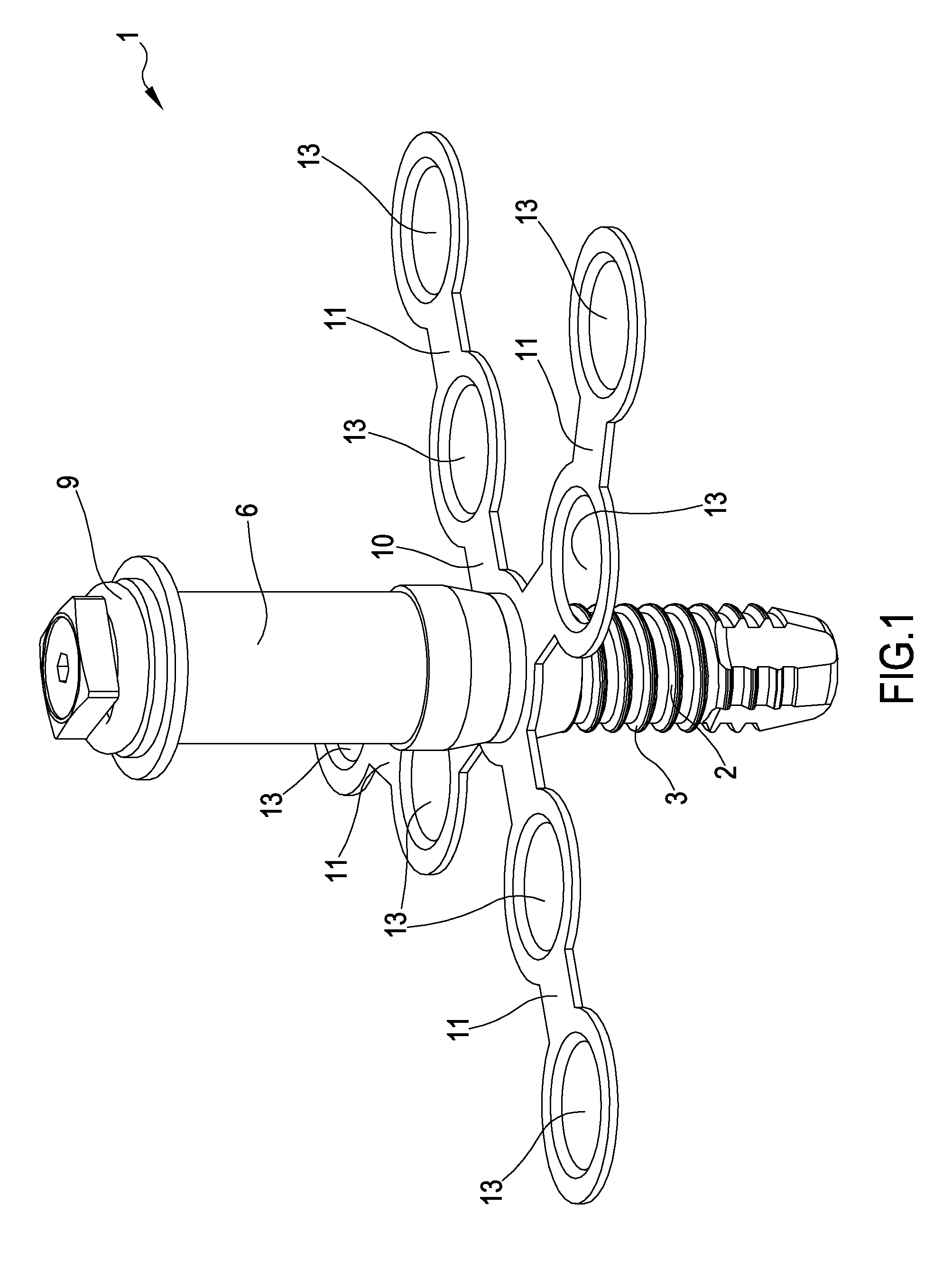
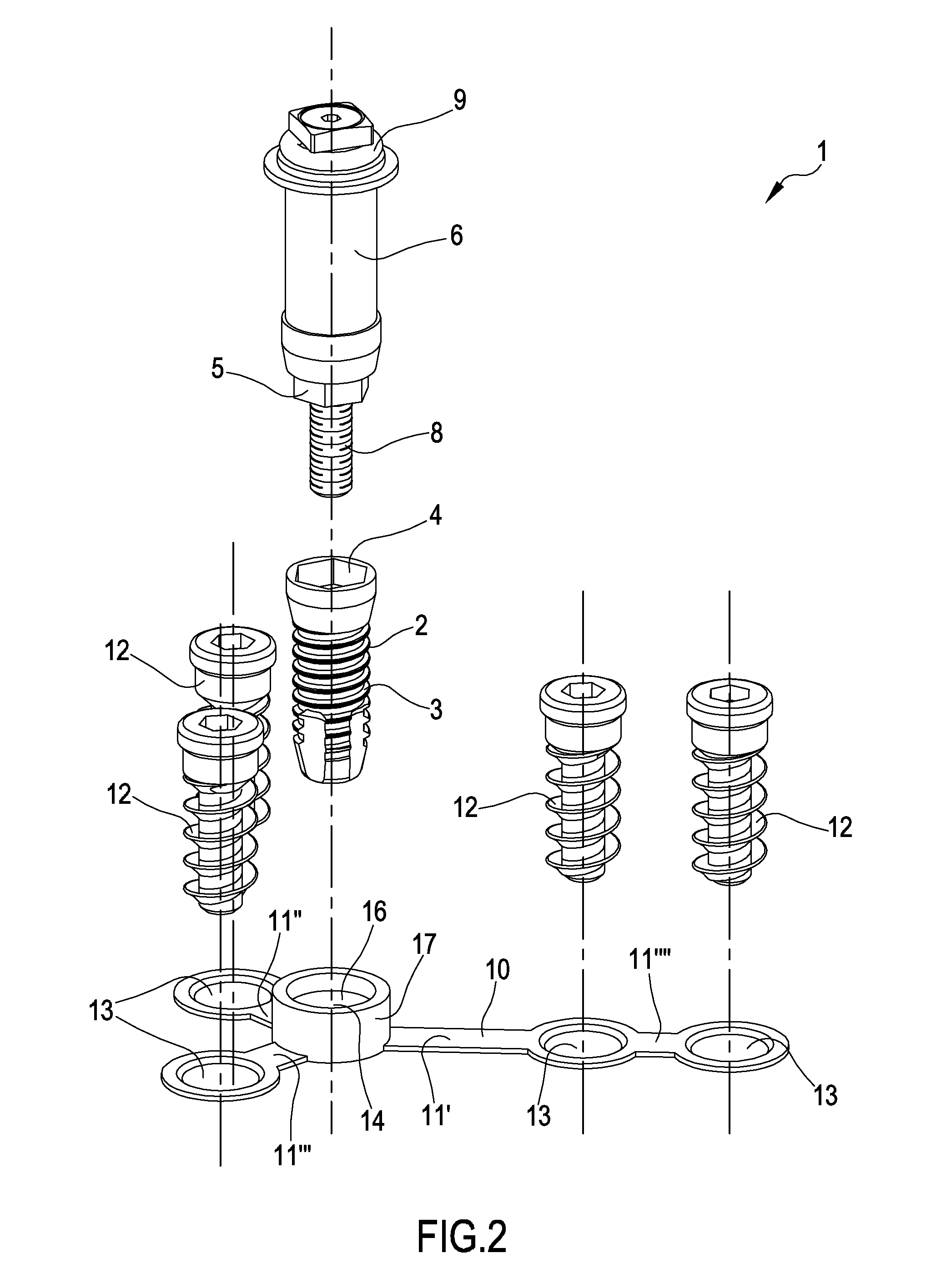
[0021]With reference to the attached figures, reference 1 shows a dental implant. Generally the dental implant 1 is destined to be applied in the mandibular or maxillary bone of a patient who lost one or more teeth which therefore must be substituted.

[0022]The dental implant 1 comprises a main body 2, preferably having an elongated shape, for example a generally cylindrical or frustoconical, or partially cylindrical and partially conical shape, destined to be implanted in a suitable primary implant seat formed in the mandibular or maxillary bone of the patient. The primary implant seat is previously formed by suitable dental tools, such as cutters or similar. For the purpose of ensuring to fix the main body 2 in the primary implant seat, it preferably comprises an outer thread 3 such to enable to screw the main body 2 in the primary implant seat, which was already threaded. Alternatively, the outer thread 3 can be of the self-tapping type, in order to form the thread in the primary ...


PUM


Abstract

The present invention refers to a dental implant (1) comprising:•—a main body (2) suitable for being implanted in a primary implant seat formed in a mandibular or maxillary bone of a patient, in order to form an artificial root for an artificial tooth;•—an auxiliary plate (10) comprising one or more portions (11) laterally protruding relative to the main body (2) and foldable by deflection, so that they can be positioned at secondary bony fixing zones at a distance from the primary implant seat when the main body (2) is implanted in the primary implant seat;•—means (12) for fixing the one or more auxiliary plates (10) protruding portions (11) in corresponding one or more auxiliary implant seats formed in the secondary bony fixing zones, wherein said one or more protruding portions (11) of the auxiliary plate (10) comprise respective second through holes (13) for fixing by means of fixing screws (12) the auxiliary plate (10) in the one or more auxiliary implant seats formed in the secondary bony fixing zones, said through holes (13) and the heads of said fixing screws (12) having a frustoconical trend, such to form a conical-type, rigid, interference fitting between the fixing screws (12) and the auxiliary plate (10).

Description

TECHNICAL FIELD OF THE INVENTION[0001]The present invention refers to a dental implant for rehabilitating patients affected by complete or partial edentulism, in other words the loss or absence of one or more teeth.PRIOR ART[0002]Dental implants to be generally applied in the mandibular or maxillary bone of patients who have lost or have experienced a damage to one or more teeth are known.[0003]A type of known implant comprises a cylindrical or conical screw, normally made of titanium, to be screwed in a suitable threaded seat previously formed in the mandibular or maxillary bone of the patient. The screw has the function of forming an artificial root for an artificial tooth, which is applied, normally by a stump screwable in a suitable seat of the screw, to an end of the screw itself once the latter has been completely osteointegrated.[0004]However, such type of dental implant has functional limits in case the implant is applied in a zone wherein the quantity of bone is scarce, par...

Claims


Application Information

Patent Timeline
IPC IPC(8): A61C8/00A61B17/86A61B17/80
CPCA61C8/0009A61C8/0027A61C8/0054A61B17/86A61C8/0069A61B17/8071A61C8/0006A61C8/0031A61C8/0096
Inventor ZANNA, MASSIMO
Owner ZANNA MASSIMO
Why Eureka
Try Eureka