Homogeneous EMI vent panel and method for preparation thereof

a technology of emi shielding and vent panel, which is applied in the field of homogeneous emi shielded vent, can solve the problems of affecting the operation of other proximities, affecting the emi shielding effectiveness of the enclosure, and foreign object debris being created in the current vent panel, so as to achieve reliable emi shielding and air flow characteristics.

Inactive Publication Date: 2016-09-01
PARKER HANNIFIN CORP
View PDF2 Cites 16 Cited by
  • Summary
  • Abstract
  • Description
  • Claims
  • Application Information

AI Technical Summary

Benefits of technology

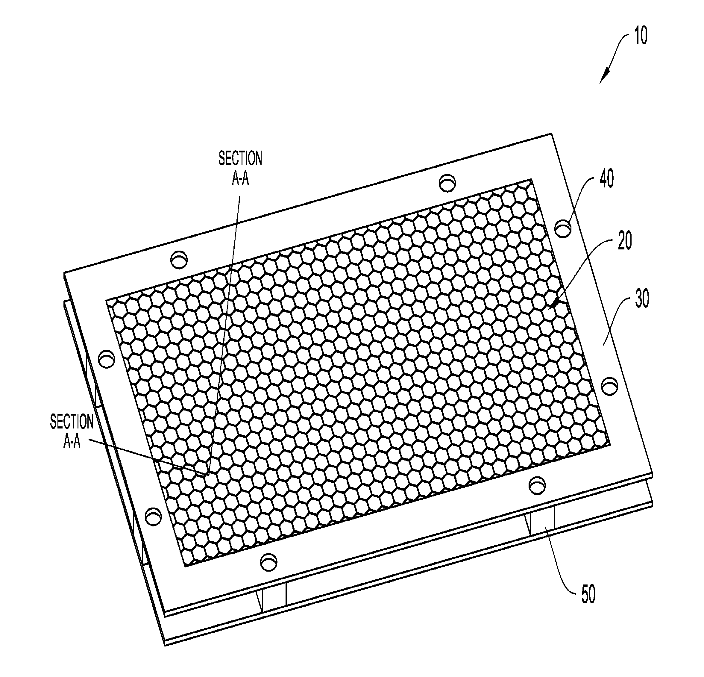
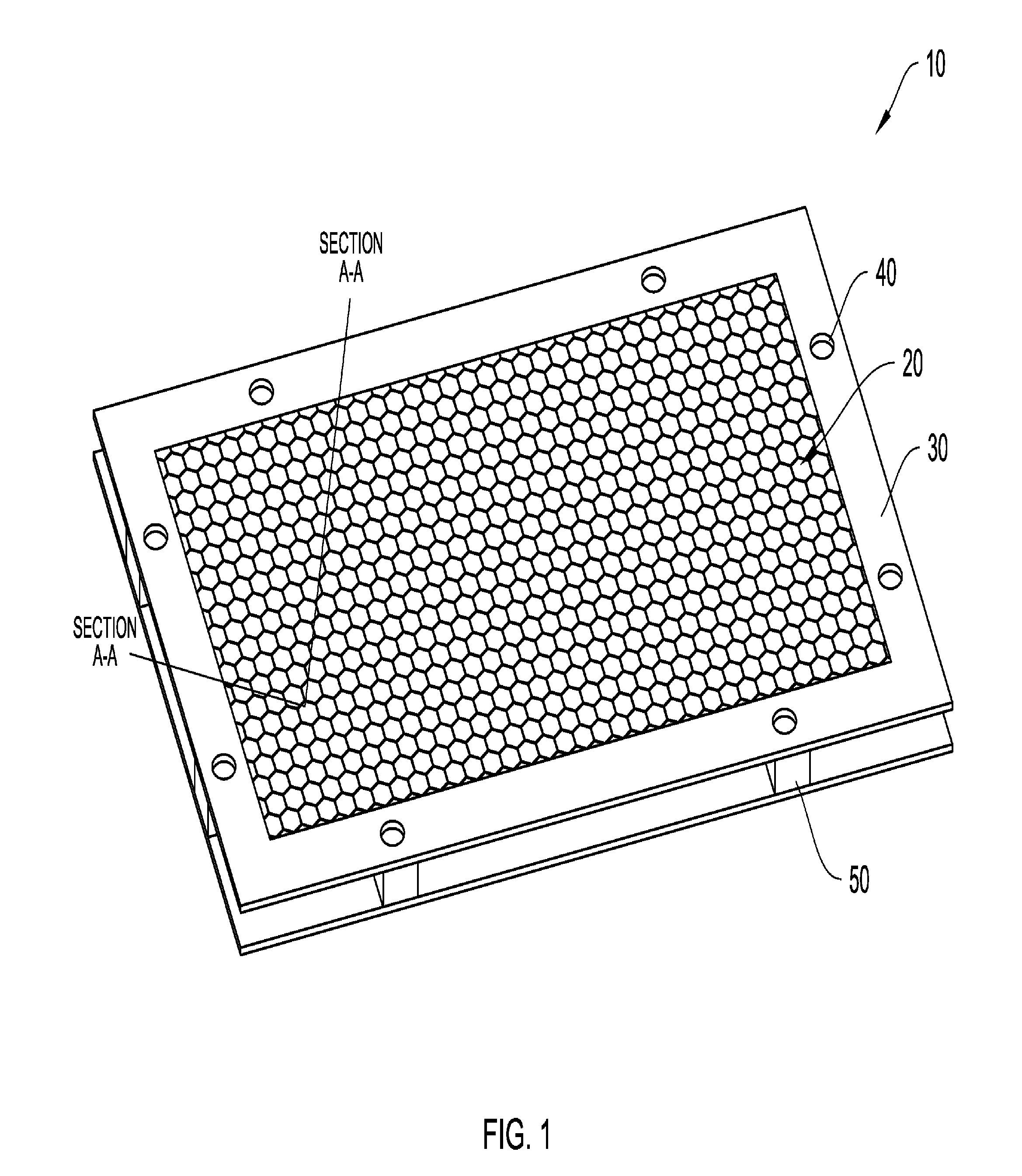
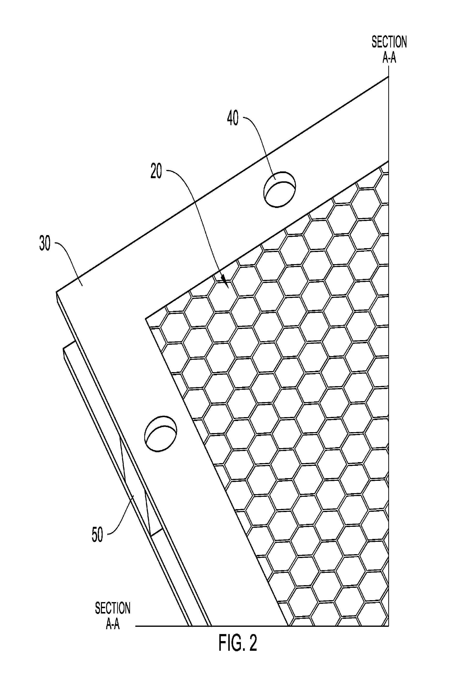
[0017]The homogenous or unitary vent panel of the invention avoids the use of solders, conductive adhesives or mechanical devices required to attach the media to the frame, while permitting reliable EMI shielding and air flow characteristics. The vent panel is therefore suitable for use as an enclosure for computer and electronics components and systems, and can avoid the creation of potential foreign object debris (“FOD”) which would occur when mounting and assembling vent panels having multiple components.
[0019]In another embodiment, the vent panel is fabricated using a selective laser sintering (“SLS”) technique. This technique enables the fabrication of the part as a single or homogeneous object even though there are numerous complex cells comprising the media structure.

Problems solved by technology

Foreign object debris is created in current vent panels, which are constructed from a separate frame and filter media, when these separate components are cut and installed.
EMI is known to interfere with the operation of other proximate electronic devices.
However, when such circuitry is contained within the confined space of an enclosure, it often is necessary to provide a cooling or ventilation means to dissipate the heat which is generated by the circuitry.
Left uncovered, such openings would represent a discontinuity in the surface and ground conductivity of the enclosure, with the result of a decrease in the EMI shielding effectiveness of the enclosure.
Indeed, as the processing speeds of electronic devices continue to increase with the attendant generation of higher frequency EMI radiation and greater heat output, enclosure designers are faced with the seemingly competing requirements of providing both adequate ventilation and effective EMI shielding.
This type of fabrication has not heretofore been possible due to issues of cost and fabrication technique limitations.

Method used


Image

  • Homogeneous EMI vent panel and method for preparation thereof
  • Homogeneous EMI vent panel and method for preparation thereof
  • Homogeneous EMI vent panel and method for preparation thereof

Examples


Embodiment Construction

[0026]Certain terminology may be employed in the following description for convenience rather than for any limiting purpose. For example, the terms “forward” and “rearward”, “front” and “rear”, “right” and “left”, “upper” and “lower,”“top” and “bottom,” and “right” and “left” designate directions in the drawings to which reference is made, with the terms “inward,”“inner,”“interior “inboard” and “outward,”“outer,”“exterior,”“outside,” or “outboard” referring, respectively, to directions toward and away from the center of a referenced element, the terms “radial” or “vertical” and “axial” or “horizontal” referring, respectively, to directions or planes perpendicular and parallel to the longitudinal central axis of a referenced element, i.e. along an x-axis and a y-axis (commonly the length and width). The “thickness” of an element is intended to denote a direction along a z-axis which extends vertically from the plane of the x-axis and y-axis. Terminology of similar import other than t...


PUM

PropertyMeasurementUnit
radio frequencyaaaaaaaaaa
frequenciesaaaaaaaaaa
thicknessaaaaaaaaaa

Abstract

A homogeneous EMI shielded vent panel is provided. The vent panel has an interior porous section and an exterior frame for attachment to an opening of an electronic enclosure. The vent panel can be fabricated using selective laser sintering technology to avoid the use of multiple parts and components which can generate harmful foreign object debris during fabrication and mounting of the vent panel.

Description

CROSS-REFERENCE TO RELATED APPLICATIONS[0001]This application is a continuation of U.S. application Ser. No. 14 / 331,604 filed Jul. 15, 2014 which claims priority to U.S. Provisional Patent Application No. 61 / 870,484 filed Aug. 27, 2013, the disclosures of which are incorporated herein in their entireties by reference thereto.BACKGROUND OF THE INVENTION[0002]The present invention relates to a homogeneous EMI shielded vent comprising an electrically conductive frame element and a porous shielding element. The vent structure is formed as a single integrated and homogenous part using a selective laser sintering (SLS) technique. The vent structure of the invention can be formed into a variety of complex shapes and configurations, and does not require the use of solders, conductive adhesives, or mechanical bonding techniques frequently used for fabricating EMI vent panels. Advantageously, the porous shielding element is a honeycomb structure containing interconnected cells providing both ...

Claims


Application Information

Patent Timeline
Patent Type & Authority Applications(United States)
IPC IPC(8): B22F3/105B22F5/10B23K26/342H05K9/00
CPCB22F3/1055H05K9/0041B33Y80/00B23K26/342B33Y10/00B22F5/10B33Y50/00G06Q30/0269Y02P10/25B22F10/20
Inventor COPPOLA, STEPHEN J.
Owner PARKER HANNIFIN CORP
Why Eureka
Try Eureka