Sheet Conveyer and Image Reading Apparatus

US20160251175A1Active Publication Date: 2016-09-01BROTHER KOGYO KK

Image

  • Sheet Conveyer and Image Reading Apparatus
  • Sheet Conveyer and Image Reading Apparatus
  • Sheet Conveyer and Image Reading Apparatus

Examples


Embodiment Construction

[0024]Hereafter, a sheet conveyer and an image reading apparatus according to an embodiment will be described with reference to the accompanying drawings.

[0025][Configuration of Multifunction Peripheral]

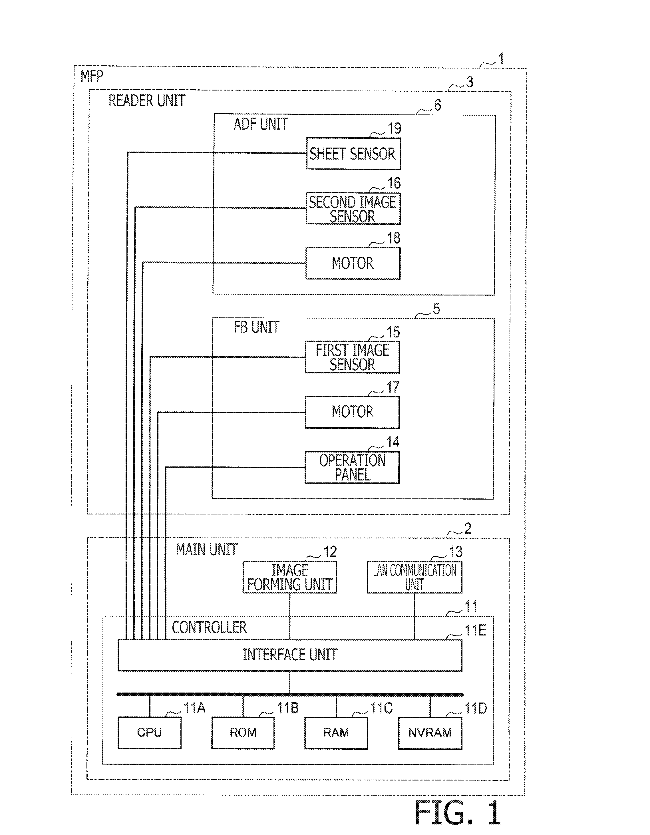
[0026]A multifunction peripheral (MFP) 1 shown in FIG. 1 is provided with the sheet conveyer and the image reading apparatus according to the embodiment. The MFP 1 includes a main unit 2 and a reader unit 3. The reader unit 3 includes a flatbed (FB) unit 5 and an auto-document feeder (ADF) unit 6.

[0027]The main unit 2 includes a controller 11. The controller 11 may include a known central processing unit (CPU) 11A, a read-only memory (ROM) 11B, a random-access memory (RAM) 11C, a non-volatile RAM (NVRAM) 11D, and an interface unit 11E. The CPU 11A may execute predetermined processes according to controlling programs, which may be stored in the ROM 11B and the RAM 11C, in order to control behaviors of each part and component in the MFP 1.

[0028]The controller 11 may control behaviors o...


PUM


Abstract

A sheet conveyer including a sheet support, a pickup roller, a separator roller, a holder, a guide, an urging member, and a contact section is provided. The holder is swingable and supports the pickup roller rotatably. The guide is attached to the holder and movable to swing relatively to the holder along with a swing movement of the holder. Urging force from the urging member acts on the guide to move toward a first position with respect to the holder. The contact section contacts a contacting part in the guide to restrict, the contacting part from being moved along with the swing movement of the holder. The guide is movable relatively to the holder from a position closer to the first position toward a position closer to a second position against the urging force from the urging member and allows the holder to further move toward the uppermost position.

Description

CROSS-REFERENCE TO RELATED APPLICATION[0001]This application claims priority under 35 U.S.C. §119 from Japanese Patent Application No. 2015-038850, filed on Feb. 27, 2015, The entire subject matter of the application is incorporated herein by reference.BACKGROUND[0002]1. Technical Field[0003]The following disclosure relates to a sheet conveyer and an image reading apparatus.[0004]2. Related Art[0005]A sheet conveyer having a pickup roller, to pick up sheets from a sheet support section and convey the sheets downstream in a conveying direction, and a separator roller, to separate the sheets conveyed by the pickup roller one by one and convey the sheets further downstream in the conveying direction, is known.[0006]The pickup roller may be rotatably supported by a holder. The holder may be supported to be swingable about an axis which is coincident with a support shaft being a rotation center of the separator roller. The pickup roller may swing together with the holder, and thereby a g...

Claims


Application Information

Patent Timeline
01 Sep 2016
Publication
US20160251175A1
IPC
B65H3/06; B65H5/06
CPC
B65H5/062; B65H3/0684; B65H3/06; B65H3/0661; B65H3/5223; B65H3/66; B65H5/068; B65H2801/06
Inventors
KUROKAWA, KOTARO