Image forming apparatus and image forming method

Inactive Publication Date: 2007-07-26
RICOH KK
View PDF11 Cites 15 Cited by
  • Summary
  • Abstract
  • Description
  • Claims
  • Application Information

AI Technical Summary

Benefits of technology

[0014]Accordingly, an object of the present invention is to provide an image forming apparatus and an image forming method, capable of producing high-durability and high-definition im

Problems solved by technology

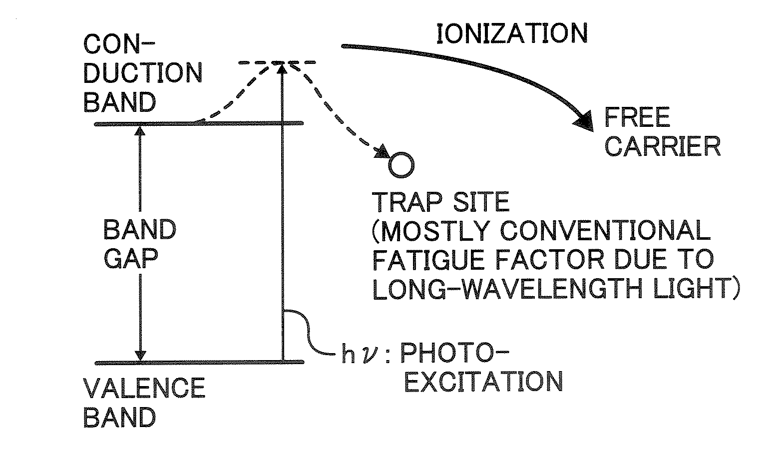
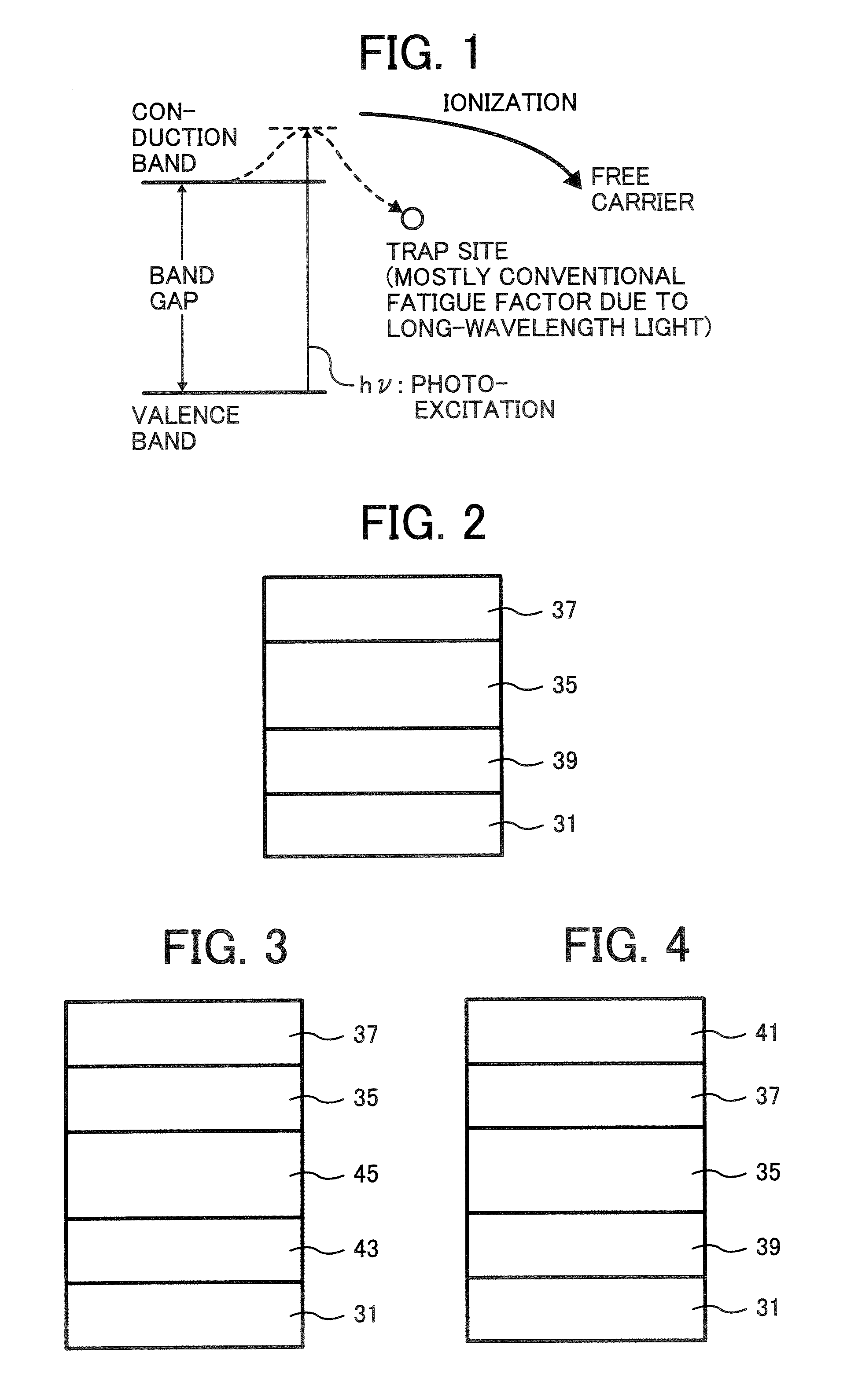
The former could be realized with the writing light source emitting short-wavelength light, but the latter is not fully solved yet.
However, the electrostatic fatigue of a photoreceptor largely depends not only on the formulation of the layers thereof bu

Method used


Image

  • Image forming apparatus and image forming method
  • Image forming apparatus and image forming method
  • Image forming apparatus and image forming method

Examples


Example

Synthesis Example 1

[0350]A titanylphthalocyanine crystal was prepared by the method disclosed in Synthesis Example 1 of Published Unexamined Japanese Patent Application No. 2001-19871. Specifically, at first 29.2 g of 1,3-diiminoisoindoline and 200 ml of sulfolane were mixed. Then 20.4 g of titanium tetrabutoxide was dropped into the mixture under a nitrogen gas flow. The mixture was then heated to 180° C. and a reaction was performed for 5 hours at a temperature of from 170 to 180° C. while agitating. After the reaction, the reaction product was cooled, followed by filtering. The thus prepared wet cake was washed with chloroform until the cake colored blue. Then the cake was washed several times with methanol, followed by washing several times with hot water heated to 80° C. and drying. Thus, a crude titanylphthalocyanine was prepared. One part of the thus prepared crude titanylphthalocyanine was dropped into 20 parts of concentrated sulfuric acid to be dissolved therein. The solut...

Example

Synthesis Example 2

[0360]A titanylphthalocyanine crystal was prepared by the method disclosed in Example 1 of Published Unexamined Japanese Patent Application No. 2004-83859.

[0361]Specifically, 60 parts of the thus prepared aqueous paste of the titanylphthalocyanine pigment prepared in Synthesis Example 1 was added to 400 g of tetrahydrofuran (THF) and the mixture was strongly agitated with a HOMOMIXER (MARK IIf from Kenis Ltd.) at a revolution of 2,000 rpm until the color of the paste was changed from navy blue to light blue. The color was changed after the agitation was performed for about 20 minutes. In this regard, the ratio of the titanylphthalocyanine pigment to the crystal change solvent (THF) is 44. The dispersion was then filtered under a reduced pressure. The thus obtained cake on the filter was washed with tetrahydrofuran to prepare a wet cake of a titanylphthalocyanine crystal. The crystal was dried for 2 days at 70° C. under a reduced pressure of 5 mmHg. Thus, 8.5 parts...

Example

Dispersion Preparation Example 1

[0366]

Formula of dispersionTitanylphthalocyanine (Pigment 1)15Polyvinyl butyral10(BX-1 from Sekisui Chemical Co., Ltd.)2-butanone280

[0367]At first, the polyvinyl butyral resin was dissolved in the solvent. The solution was mixed with phthalocyanine crystal and the mixture was subjected to a dispersion treatment for 30 minutes using a bead mill DISPERMAT SL-05C1-EX from VMA-Getzmann GmbH, including PSZ balls having a diameter of 0.5 mm and rotating at a revolution of 1200 rpm to prepare a dispersion 1.


PUM


Abstract

An image forming apparatus including
    • a photoreceptor including
      • a substrate, and
      • an intermediate layer,
      • a charge generation layer, and
      • a charge transport layer on the substrate in this order;
    • a charger charging the photoreceptor; an irradiator irradiating the photoreceptor to form an electrostatic latent image thereon;
    • an image developer developing the electrostatic latent image with a toner to form a toner image on the photoreceptor;
    • a transferer transferring the toner image onto a recording medium;
    • a fixer fixing the toner image on the recording medium; and
    • a discharger removing a residual potential from the photoreceptor with light,
    • wherein the intermediate layer includes a metal oxide, the charge generation layer comprises an organic charge generation material, and the irradiator irradiates the photoreceptor with writing light having a wavelength shorter than 450 nm, which is not absorbed in the metal oxide in the intermediate layer.

Description

BACKGROUND OF THE INVENTION[0001]1. Field of the Invention[0002]The present invention relates to an image forming apparatus and an image forming method using an electrostatic latent image bearer (hereinafter referred to as an “electrophotographic photoreceptor”, a “photoreceptor” or a “photoconductive insulator”) having a photosensitive layer comprising a charge generation layer and a charge transport layer, wherein the charge generation layer comprises an organic charge generation material.[0003]2. Discussion of the Background[0004]Recently, development of information processing systems utilizing electrophotography is remarkable. In particular, optical printers in which information converted to digital signals is recorded using light have been dramatically improved in print qualities and reliability. This digital recording technique is applied not only to printers but also to copiers, and so-called digital copiers have been developed and used. Copiers utilizing both the conventiona...

Claims


Application Information

Patent Timeline
IPC IPC(8): G03G15/14
CPCG03G5/142G03G2215/00957G03G5/144
Inventor NIIMI, TATSUYA
Owner RICOH KK
Why Eureka
Try Eureka