
High-frequency front end circuit

Inactive Publication Date: 2016-09-01
MURATA MFG CO LTD
View PDF16 Cites 3 Cited by
  • Summary
  • Abstract
  • Description
  • Claims
  • Application Information

AI Technical Summary

Benefits of technology

The present disclosure describes a front end circuit that can reduce interference with communication using desired frequency bands, even when there are frequency bands close to the desired bands. This is achieved by placing the second communication antenna close to the main antenna, so that signals with the second frequency bands are less likely to affect the reception of signals with the first frequency band. Overall, this improves the signal-to-noise ratio of the reception signals and ensures effective communication even in challenging frequency environments.

Problems solved by technology

In the case where a frequency band of the cellular communication and a frequency band of the wireless LAN communication are close to each other, mutual interference is likely to occur.
In particular, in the case where a frequency range of a transmission signal of wireless LAN communication and a frequency range of a reception signal of cellular communication are close to each other, the transmission signal of the wireless LAN communication may sneak into a reception circuit for cellular communication, thereby causing deterioration in the receiving sensitivity of cellular communication.

Method used


Image

  • High-frequency front end circuit
  • High-frequency front end circuit
  • High-frequency front end circuit

Examples


Embodiment Construction

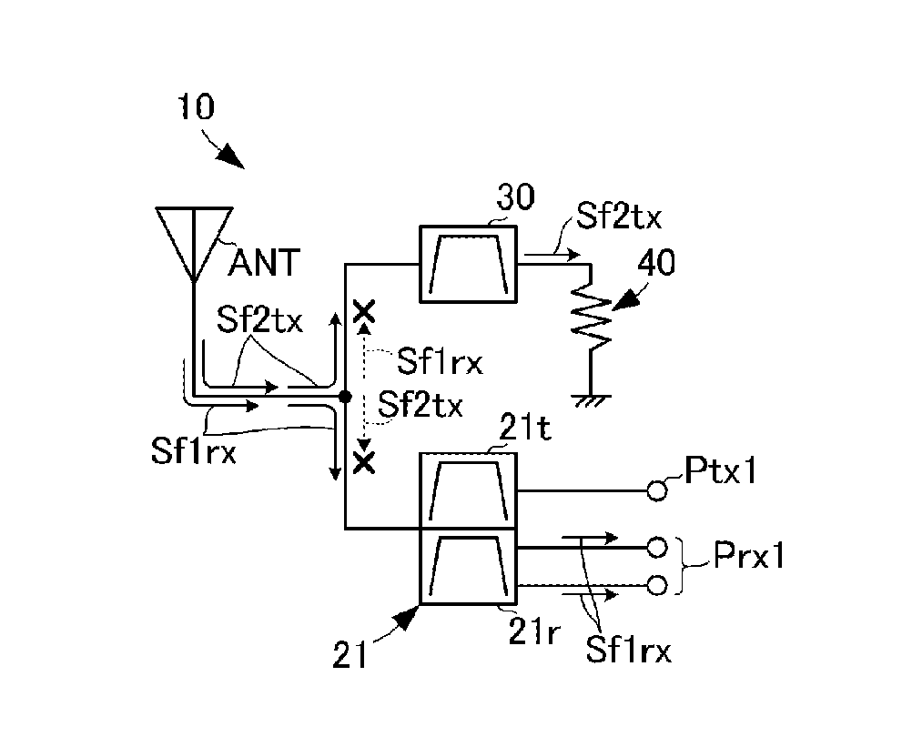
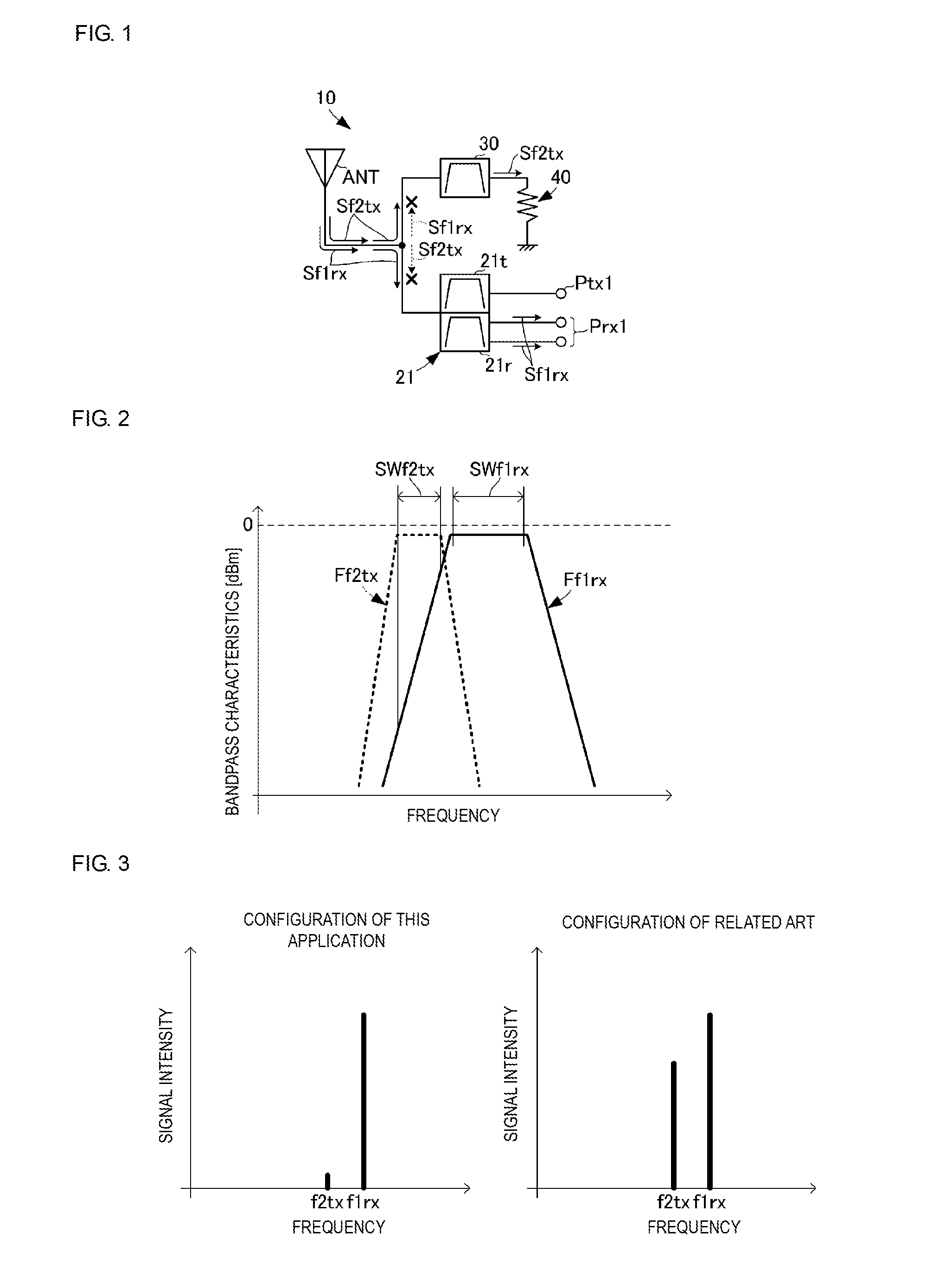
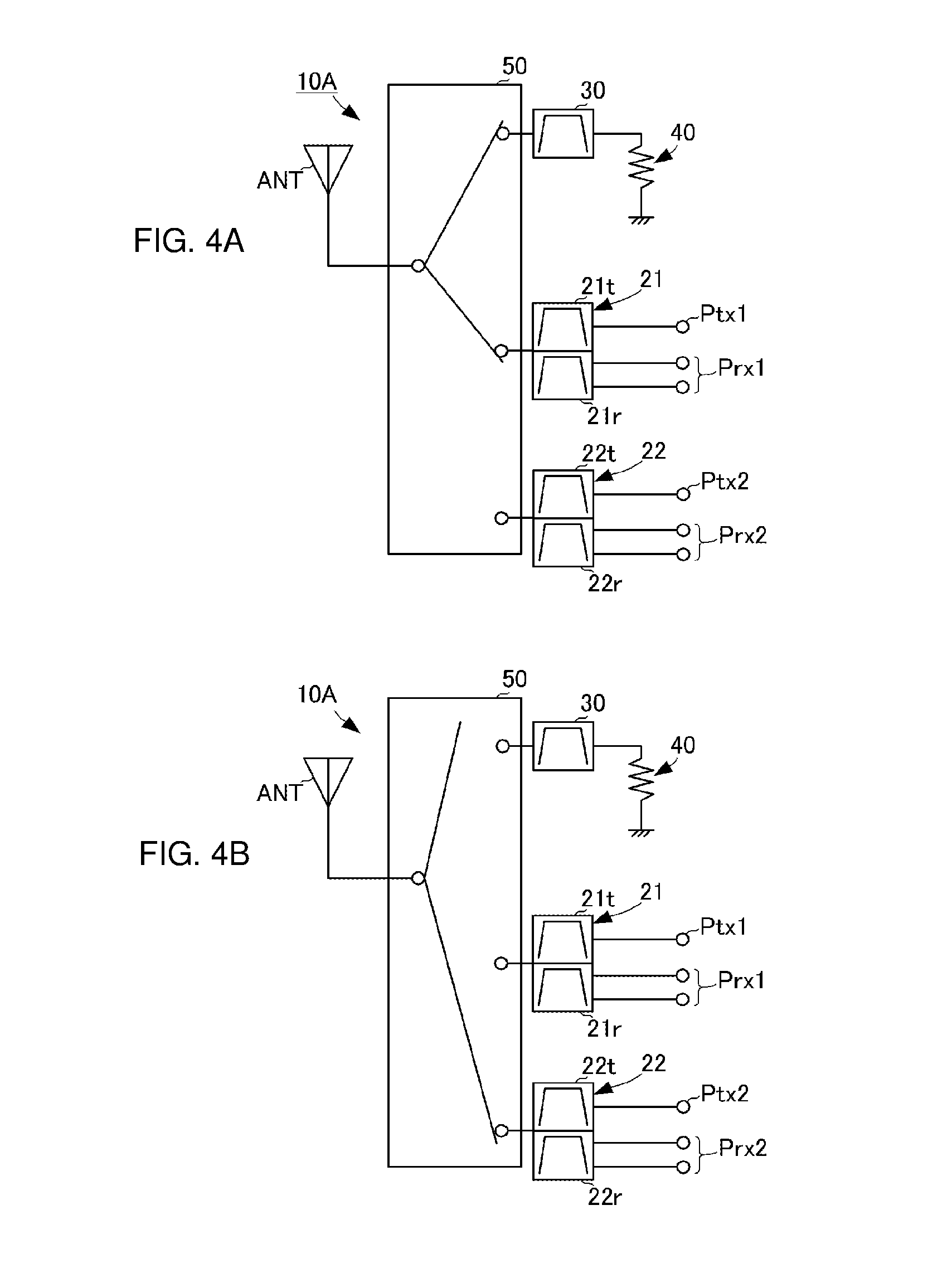
[0027]A high-frequency front end circuit according to a first embodiment of the present disclosure will be described with reference to drawings. FIG. 1 is a circuit block diagram of a high-frequency front end circuit according to the first embodiment of the present disclosure. FIG. 2 is a diagram illustrating bandpass characteristics of each filter of the high-frequency front end circuit according to the first embodiment of the present disclosure.

[0028]A high-frequency front end circuit 10 according to this embodiment includes a duplexer 21, a filter 30, a terminating resistor 40, an antenna ANT, a first transmission signal input terminal Ptxl, and a first reception signal output terminal Prxl. The duplexer 21 includes a transmission-side filter 21t and a reception-side filter 21r. The reception-side filter 21r corresponds to a “first filter” of the present disclosure, and the filter 30 corresponds to a “second filter” according to the present disclosure.

[0029]The antenna ANT is con...


PUM


Abstract

An antenna of a high-frequency front end circuit is connected to a duplexer and a filter. A reception-side filter of the duplexer is connected to a first reception signal output terminal. The filter is connected to the ground with a terminating resistor interposed there between. The reception-side filter is a filter which has a pass band including a frequency range of a reception signal having a first frequency band. The filter is a filter which has a pass band including a frequency range of a communication signal having a second frequency band and which has an attenuation range including the frequency range of the reception signal having the first frequency band.

Description

BACKGROUNDTechnical Field[0001]The present disclosure relates to a high-frequency front end circuit which performs at least one of transmission and reception of a high-frequency signal.[0002]Nowadays, there are various communication specifications such as a cellular system and a wireless LAN system for wireless communications, and multiple types of frequency bands are used. In order to cope with such various communication specifications and frequency bands, for example, a cellular phone device having a circuit configuration described in Patent Document 1 has been put into practical use.[0003]The cellular phone device described in Patent Document 1 includes a cellular antenna and a wireless LAN antenna. A cellular transmission / reception circuit is connected to the cellular antenna, and a wireless LAN transmission / reception circuit is connected to the wireless LAN antenna.[0004]Such cellular phone devices may perform cellular communication and wireless LAN communication simultaneously...

Claims


Application Information

Patent Timeline
IPC IPC(8): H04B1/00H04L5/14H04W84/12H04B1/50
CPCH04B1/0057H04W84/12H04L5/14H04B1/50
Inventor HAYAFUJI, HISAO
Owner MURATA MFG CO LTD
Learn More