
Audio signal amplification apparatus and method of use

Inactive Publication Date: 2016-09-01
DICKSON OMAR F
View PDF5 Cites 0 Cited by
  • Summary
  • Abstract
  • Description
  • Claims
  • Application Information

AI Technical Summary

Benefits of technology

The present invention is an audio signal amplification apparatus that is designed to prevent accidents caused by overfilling oil tanks. It amplifies the audio signal of a vent alarm whistle and sends it wirelessly to a receiver carried by an individual filling the oil tank. The device is easy to install and can be detached from a vent pipe. This innovation helps to increase awareness and prevents unauthorized access to heating oil tanks, reducing the risk of accidents and spills.

Problems solved by technology

Oils spills can result in significant damage to a homeowner's property and to the environment, both of which can be very expensive to clean up.
The cost to clean up an accidental release of heating oil can run from one thousand dollars to several hundred thousand dollars, and can take several weeks to several years to clean up, depending upon the magnitude of the spill.
As any heating oil truck driver can attest to, vent pipes are often located in uncomfortable positions / locations, often making them very difficult to hear.
Furthermore, in locations where there is loud existing background noise it can be virtually impossible to hear a conventional vent alarm.
This problem is further exacerbated by vent alarms that simply do not emit a loud enough audio signal to begin with.
While one possible approach could be to design vent alarms that give off a louder signal, such an approach would necessarily require reinstallation of all vent alarms.
Furthermore, the effectiveness of this approach would still be severely limited in situations where the difficulty hearing a vent alarm audible alert is hampered by great distances and / or loud background noise.

Method used


Image

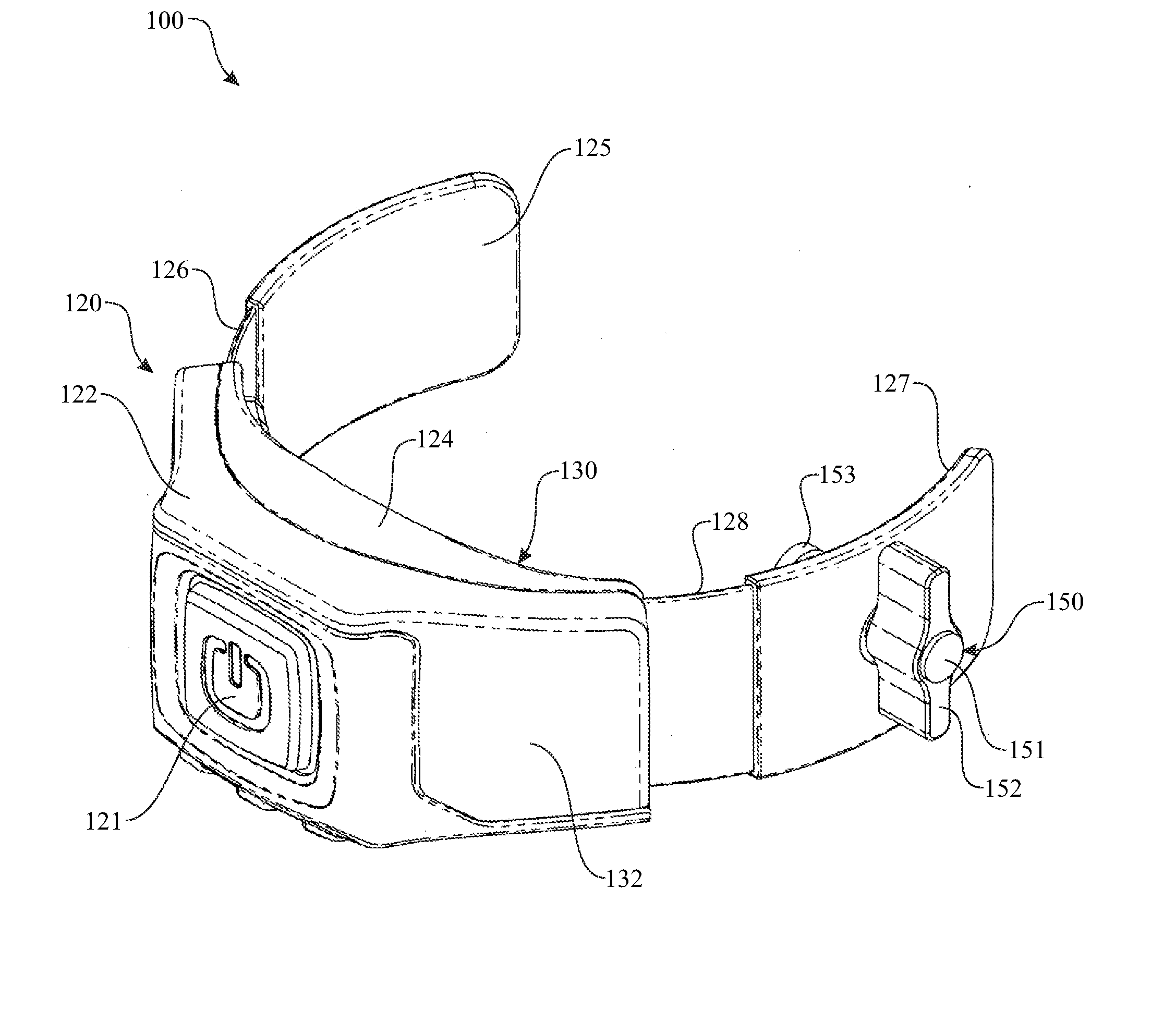
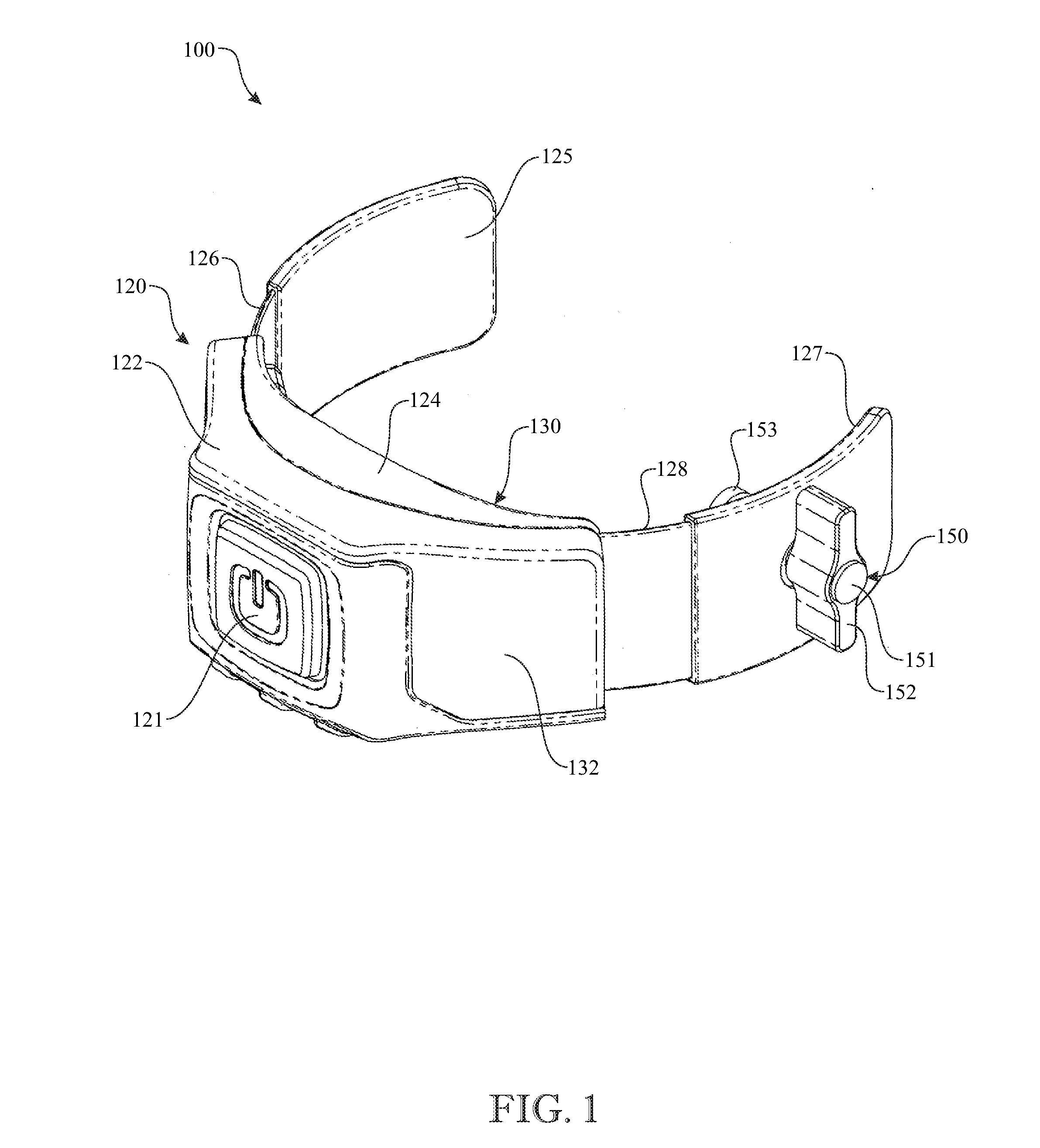
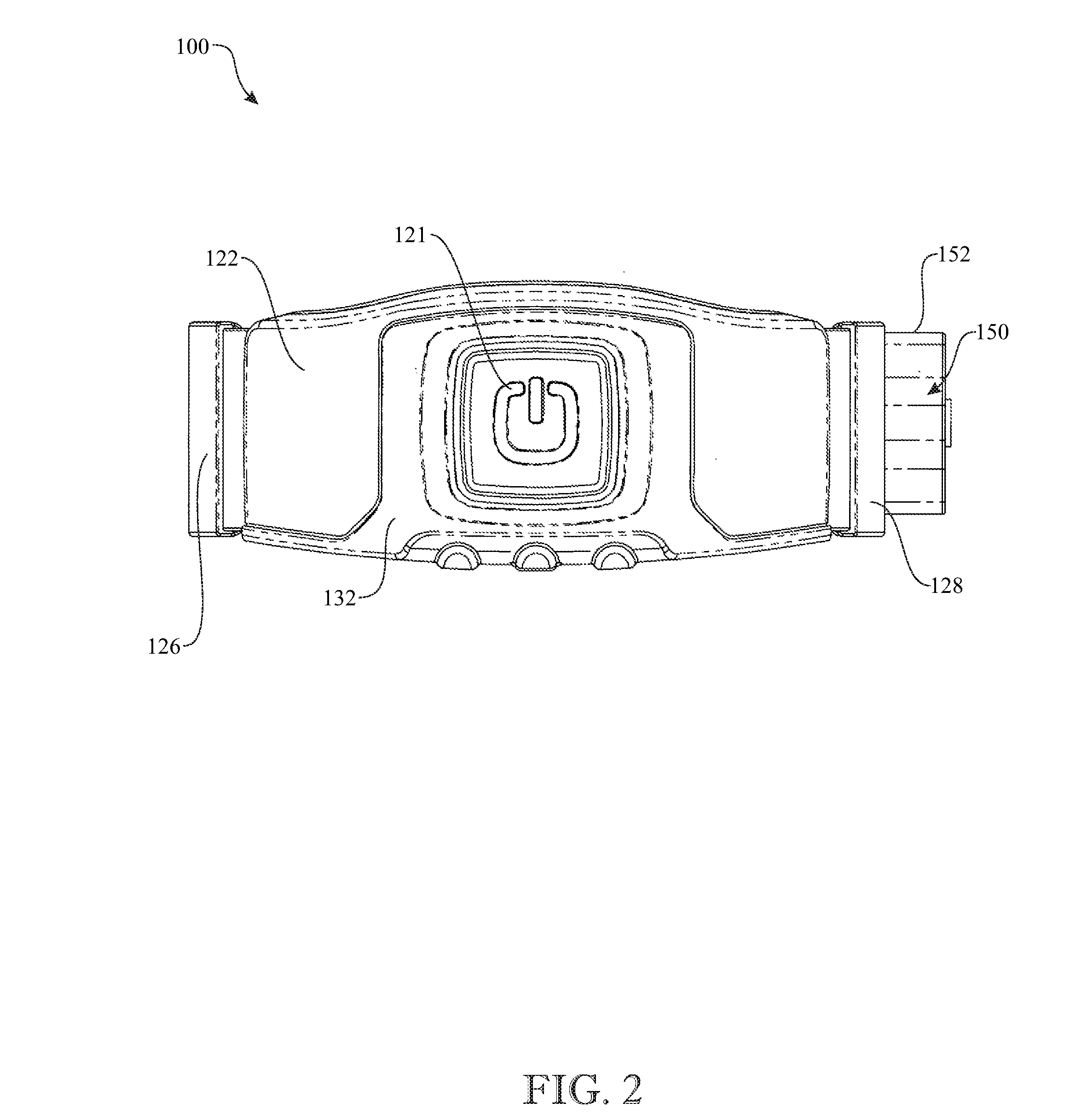
  • Audio signal amplification apparatus and method of use
  • Audio signal amplification apparatus and method of use
  • Audio signal amplification apparatus and method of use

Examples


Embodiment Construction

[0047]The following detailed description is merely exemplary in nature and is not intended to limit the described embodiments or the application and uses of the described embodiments. As used herein, the word “exemplary” or “illustrative” means “serving as an example, instance, or illustration.” Any implementation described herein as “exemplary” or “illustrative” is not necessarily to be construed as preferred or advantageous over other implementations. All of the implementations described below are exemplary implementations provided to enable persons skilled in the art to make or use the embodiments of the disclosure and are not intended to limit the scope of the disclosure, which is defined by the claims. For purposes of description herein, the terms “upper”, “lower”, “left”, “rear”, “right”, “front”, “vertical”, “horizontal”, and derivatives thereof shall relate to the invention as oriented in FIG. 1. Furthermore, there is no intention to be bound by any expressed or implied theo...


PUM


Abstract

An audio signal amplification apparatus includes a clamp body assembly for clamping onto a vent pipe of an oil tank and an amplifier control assembly having a PC board containing amplifier circuitry configured for amplifying a vent alarm sound coming from the vent pipe and wirelessly transmitting the amplified vent alarm sound to a receiver carried by a person filling the oil tank. The clamp body assembly includes a central shell subassembly supporting the PC board and a pair of curved arm members extending from opposite sides of the central shell subassembly for surrounding and clamping on a portion of the vent pipe so as to facilitate attaching the amplifier control assembly to the vent pipe. The apparatus further includes a clamp device adjustably attaching the apparatus onto a vent pipe of one of different cross-sectional sizes.

Description

CROSS REFERENCE(S) TO RELATED APPLICATION(S)[0001]This U.S. non-provisional patent application claims the benefit of U.S. provisional patent application No. 62 / 126,593, filed on Feb. 28, 2015, which is hereby incorporated-by-reference herein its entirety.FIELD OF THE INVENTION[0002]The present invention generally relates to audio amplification devices. More particularly, the invention pertains to an audio signal amplification apparatus and a method of use for amplifying an audio signal emitted from a heating oil tank vent alarm and clearly communicating the amplified audio signal to an individual that is not in close proximity to the vent alarm.BACKGROUND OF THE INVENTION[0003]Vent alarms are commonly used on residential heating oil tanks to minimize the chance of a heating oil dealer overfilling a heating oil tank and, thereby, helping to completely avoid an oil spill. Oils spills can result in significant damage to a homeowner's property and to the environment, both of which can b...

Claims


Application Information

Patent Timeline
IPC IPC(8): H04R1/02G01F23/22H04R3/00
CPCH04R1/02G01F23/22H04R3/00G01F23/0015H04R1/1008H04R2420/07G01F23/80
Inventor DICKSON, OMAR F.
Owner DICKSON OMAR F
Learn More