Devices for treating paravalvular leakage and methods use thereof

a technology for paravalvular leakage and devices, applied in the field of devices for treating paravalvular leakage, can solve the problems of valvular or paravalvular leakage, unsatisfactory leaking during heart pumping, etc., and achieve the effect of shortened distal portion and proximal portion

Inactive Publication Date: 2016-09-08
MITRALIGN INC
View PDF4 Cites 46 Cited by
  • Summary
  • Abstract
  • Description
  • Claims
  • Application Information

AI Technical Summary

Benefits of technology

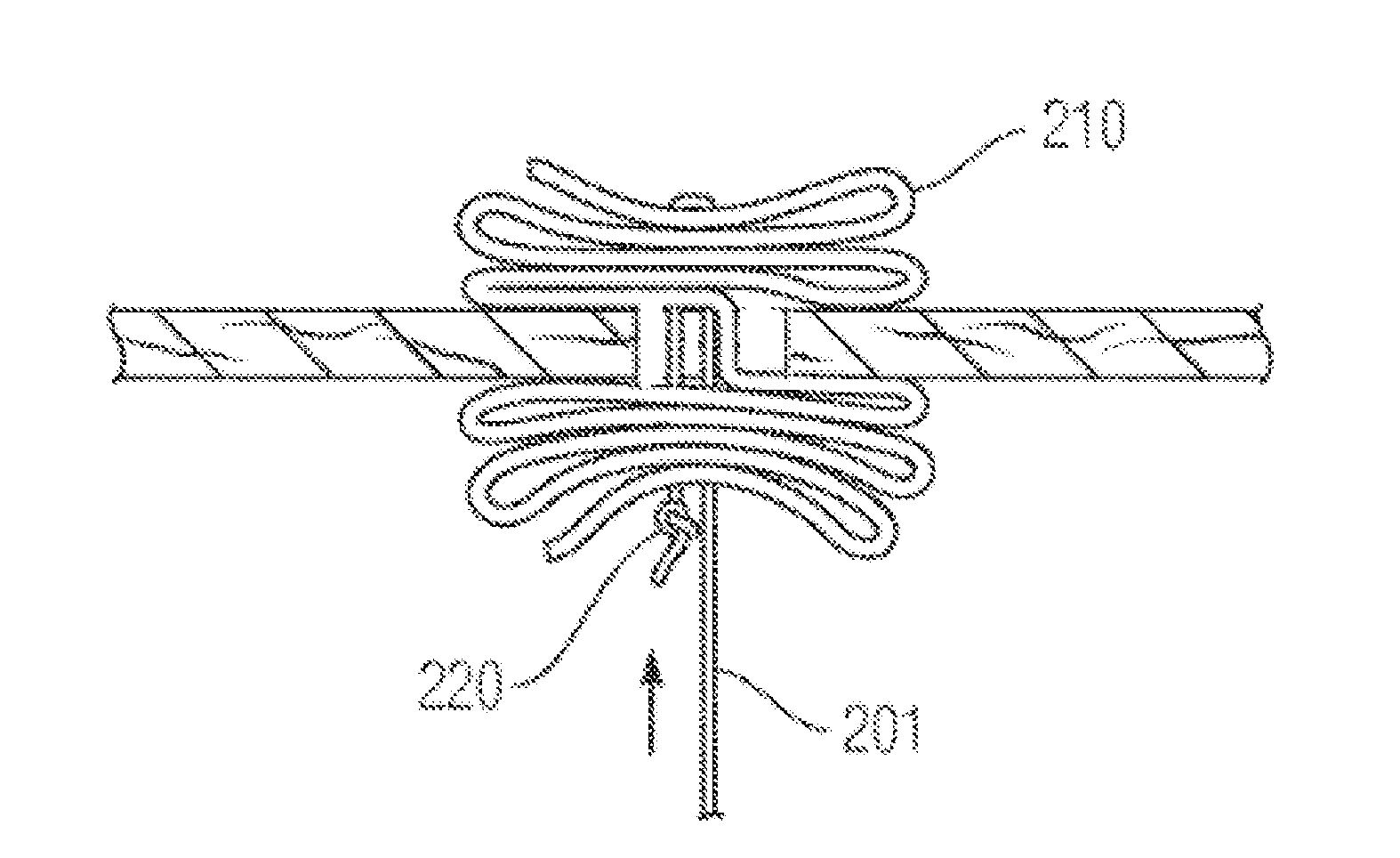
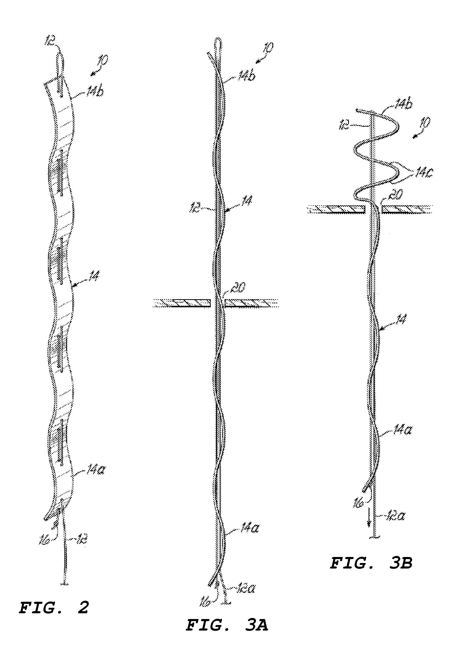
[0009]In various embodiments, the anchor includes at least one tensioning member. In some embodiments, the tensioning member causes both ends of the elongate anchor member to move towards each other. This motion can create a shortened distal portion and/or a shortened proximal portion. In certain embodiments, doing so secures the paravalvular leakage between the distal and the proximal portions of the elongate anchor member.
[0010]In embodiments where an anchor of the present teachings includes two elongate anchor members, the tensioning member causes at least one of the two elongate anchor members to move towards the other elongate anchor member. I

Problems solved by technology

This opening or space 1604 results in undesired leaking during pu

Method used


Image

  • Devices for treating paravalvular leakage and methods use thereof
  • Devices for treating paravalvular leakage and methods use thereof
  • Devices for treating paravalvular leakage and methods use thereof

Examples


Embodiment Construction

[0067]Certain specific details are set forth in the following description and Figures to provide an understanding of various embodiments of the present teachings. Those of ordinary skill in the relevant art will understand that various features of the present teachings may be used alone or in numerous combinations depending on the needs and preferences of the user. Those skilled in the art can also practice other embodiments of the present teachings without one or more of the details described below. Thus, it is not the intention of the present teachings to restrict or in any way limit the scope of the appended claims to such details. While various processes are described with reference to steps and sequences in the following disclosure, the steps and sequences of steps should not be taken as required to practice all embodiments of the present teachings.

[0068]As used herein, the term “proximal” means closest to the operator (less into the body) and “distal” means furthest from the o...


PUM


Abstract

An aspect of the present teachings includes a method of percutaneously treating a paravalvular leakage. In a preferred embodiment, the method includes providing an anchor having an elongate anchor member and a tensioning member, positioning the anchor through a paravalvular leakage, deploying the anchor wherein at least a part of the distal portion of the elongate anchor member is on one side of the paravalvular leakage, and applying tension to the tensioning member so that at least a part of the distal portion of the elongate anchor member transitions from the elongate configuration to the shortened configuration. Another aspect of the present teachings includes a device that can be used in a method of percutaneously treating a paravalvular leakage.

Description

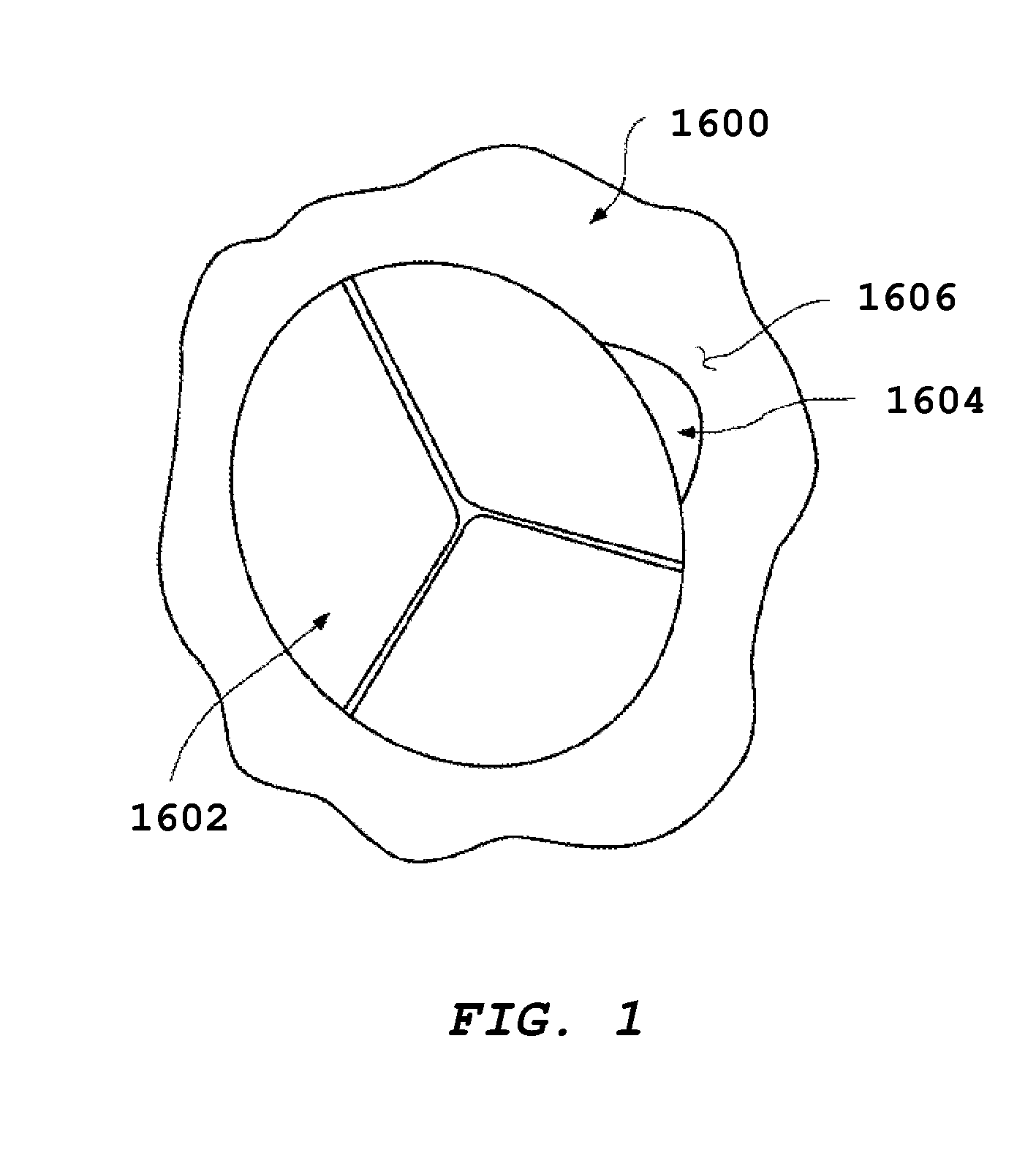
CROSS-REFERENCE TO RELATED APPLICATION[0001]This application is based on and claims priority to U.S. Provisional Patent Application 62 / 128,997, filed Mar. 5, 2015, the entire contents of which is incorporated by reference herein as if expressly set forth in its respective entirety herein.BACKGROUND[0002]Paravalvular leakage is a complication associated with the implantation of a prosthetic valve. It may occur both in traditional surgical or minimally invasive transcatheter approaches. FIG. 1 illustrates an artificial valve 1600 that may include, for example, a multi-leaflet structure 1602 and that may be implemented in an appropriate manner as will be appreciated by those of ordinary skill in the art. Additionally, a small opening or space 1604 between the heart 1606 and the valve 1600 is shown as may occur in some instances of valve replacement. This opening or space 1604 results in undesired leaking during pumping of the heart and is termed a valvular or paravalvular leak.[0003]Ac...

Claims


Application Information

Patent Timeline
IPC IPC(8): A61F2/24
CPCA61F2/246A61F2220/0075A61F2/2466A61F2/2463A61B17/0057A61B2017/00004A61B2017/00575A61B2017/00606A61B2017/00619A61B2017/0406A61B2017/0419A61F2/24A61F2250/0069A61B17/12022
Inventor CAHALANE, STEVENROBINSON, JASON
Owner MITRALIGN INC
Why Eureka
Try Eureka