
Closure for a container

a container and closure technology, applied in the field of closures, can solve the problems of inability to duplicate sensory and tactile feedback to a human, difficult for a child to perform, and inability to perform the required manipulation, so as to facilitate the use and reduce the resistance

Inactive Publication Date: 2016-09-08
RIEKE
View PDF10 Cites 2 Cited by
  • Summary
  • Abstract
  • Description
  • Claims
  • Application Information

AI Technical Summary

Benefits of technology

The patent text describes a two-cap combination for a container. The outer cap is designed to move the inner cap into position and can be advanced or removed. The force against the outer cap's movement increases as it gets closer to the inner cap, which helps to keep them in place once engaged. The text also describes a feature called CR that allows for easy removal of the inner cap without needing the outer cap. When the inner cap is placed on the container, the CR feature is not needed, so the outer cap can move more freely without added resistance. This makes it more challenging for a child to open the container than it is to close it. The technical effect of the patent text is the improved design of the two-cap combination that makes it easier to open and close the container while keeping the caps secure.

Problems solved by technology

The manner or method of engagement in order to be able to remove the inner cap from the container involves a particular movement and manipulation of the two caps which is considered difficult for a child to perform.
It is unlikely that a child will be able to perform the required manipulation in order to open the container.
However, when a liquid product is in the container, it is important that the closed condition between the inner cap and the container not be defeated by a child while playing with or manipulating the inner and outer caps.
When automated equipment is used for the capping operation, the sensory and tactile feedback to a human cannot be duplicated.
While machine torque settings can be used to presumably resolve any over-tightening issues, the safe gripping of the outer cap may be more challenging.

Method used


Image

  • Closure for a container
  • Closure for a container
  • Closure for a container

Examples


Embodiment Construction

[0043]For the purpose of promoting an understanding of the principles of the invention, reference will now be made to the embodiments illustrated in the drawings and specific language will be used to describe the same. It will nevertheless be understood that no limitation of the scope of the invention is thereby intended. Any alterations and further modifications in the described embodiments, and any further applications of the principles of the invention as described herein are contemplated as would normally occur to one skilled in the art to which the invention relates. One embodiment of the invention is shown in great detail, although it will be apparent to those skilled in the relevant art that some features that are not relevant to the present invention may not be shown for the sake of clarity.

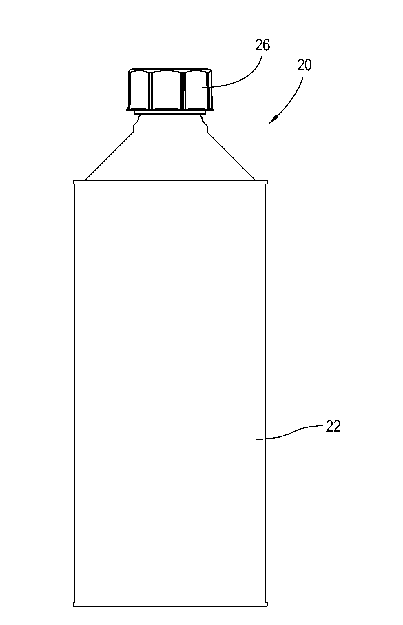
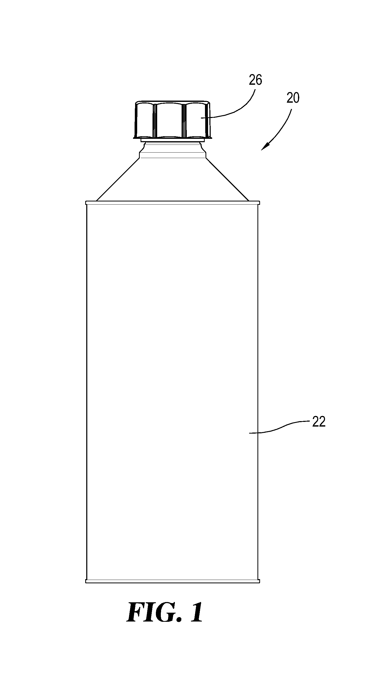
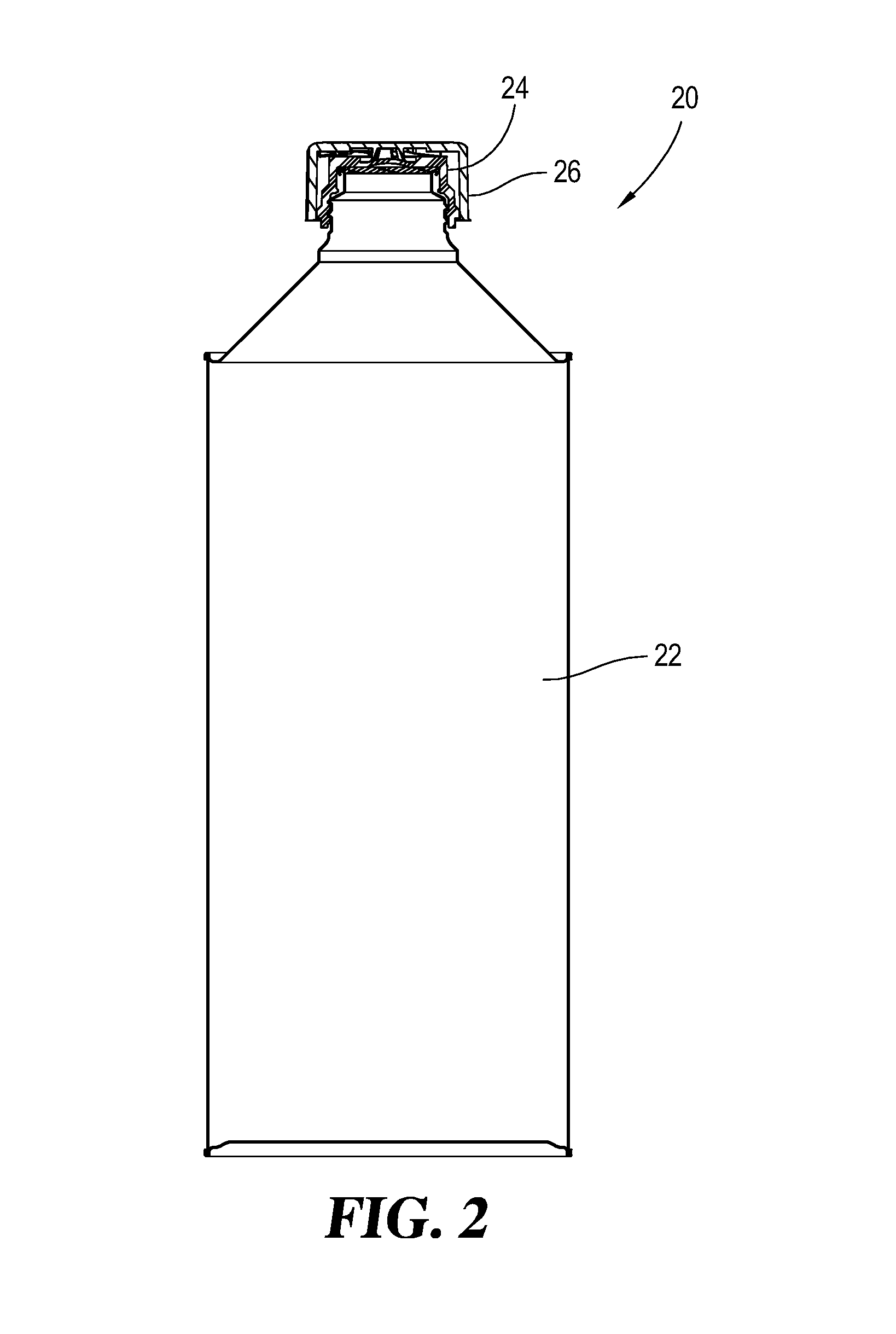
[0044]Referring to FIGS. 1-8, there is illustrated a closed container assembly 20 which is constructed and arranged to hold a liquid product. While the illustrated container is capable of...


PUM


Abstract

A closure assembly for use on a container neck finish has an inner cap which threadedly engages the neck finish and an outer cap which is received by the inner cap. Torque lugs on the outer cap cooperate with abutment formations on the inner cap such that rotation of the outer cap drives the inner cap onto the neck finish. Cooperative engagement between the two caps is achieved by downward axial movement of the outer cap. An arrangement of ramp sections on the inner cap and an arrangement of interior lugs on the outer cap provide an assist feature helping to pull the outer cap in the axially downward direction. Another feature of the closure assembly includes a spring-biasing relationship between the inner and outer caps. The inner cap also includes an abutment structure which cooperates with the container to limit drop test deformation of the container.

Description

CROSS-REFERENCE TO RELATED APPLICATION[0001]This application is a continuation of PCT Application No. PCT / US2014 / 063816, filed Nov. 4, 2014 which claims the benefit of U.S. Provisional Patent Application Ser. No. 61 / 905,488 filed Nov. 18, 2013, both of which are hereby incorporated by reference.BACKGROUND[0002]One construction for a child-resistant (CR) closure is to use a combination of an inner cap and a cooperating outer cap. When the neck finish of the corresponding container is externally threaded, the inner cap is typically constructed and arranged with internal threads which allow the inner cap to be securely assembled, by threading, onto the neck finish. Although other connection constructions between the inner cap and the container neck finish might be contemplated, the exemplary embodiment disclosed herein shows a threaded connection.[0003]In order to incorporate a child-resistant feature or capability to this inner and outer cap construction, an engagement between these t...

Claims


Application Information

Patent Timeline
Patent Type & Authority Applications(United States)
IPC IPC(8): B65D50/04B65D1/02
CPCB65D1/0246B65D50/041B65D2215/02
Inventor BAUGHMAN, GARY M.KNOUSE, SIMON C.
Owner RIEKE
Learn More