Method and system for 3D capture based on structure from motion with pose detection tool

a technology of pose detection and 3d capture, applied in the field of optical systems, can solve the problems of difficult to create a map of the environment from a series of moving camera images without some knowledge of the motion (pose) of the camera, and heavy hardware solutions have the disadvantages of being bulky and expensive, and unsuitable for small mobile consumer devices such as smart phones

Inactive Publication Date: 2016-09-08
JOVANOVIC DEJAN +4
View PDF2 Cites 56 Cited by
  • Summary
  • Abstract
  • Description
  • Claims
  • Application Information

AI Technical Summary

Problems solved by technology

Hardware-intensive solutions have the disadvantages of being bulky and expensive.
SFM systems have the disadvantage of requiring extensive computing resources or extended processing times in order to create the 3D representation, thus making them unsuitable for small mobile consumer devices such as smart phones.
These two paths are interdependent in that it is difficult to track the motion (pose) of the camera without some knowledge of the 3D environment through which it is moving, and it is difficult to create a map of the environment from a series of moving camera images without some knowledge of the motion (pose) of the camera.

Method used


Image

  • Method and system for 3D capture based on structure from motion with pose detection tool
  • Method and system for 3D capture based on structure from motion with pose detection tool
  • Method and system for 3D capture based on structure from motion with pose detection tool

Examples


first embodiment

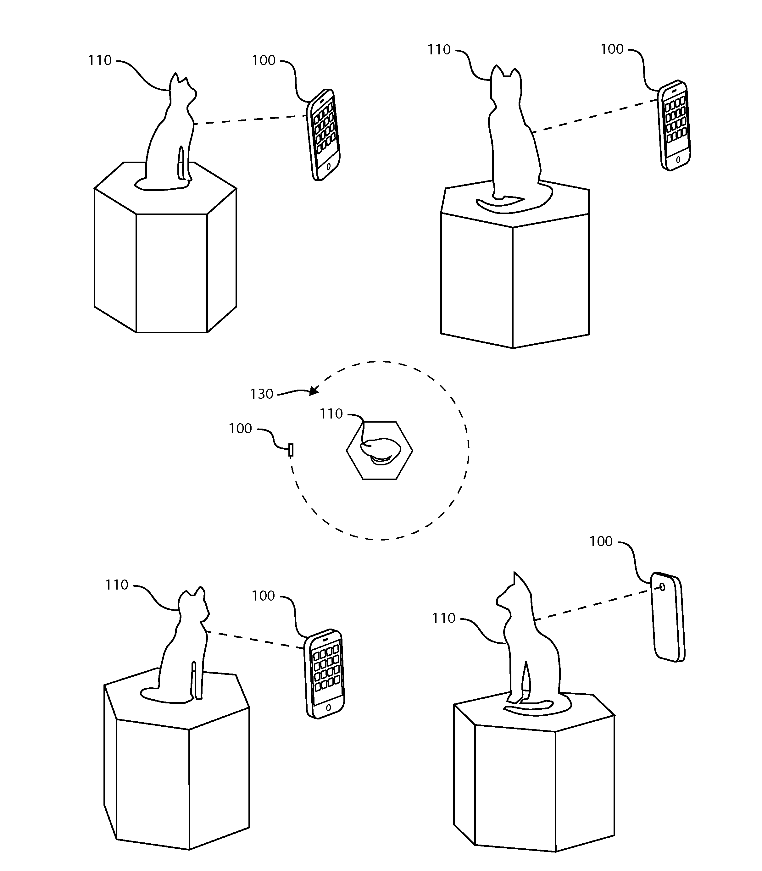
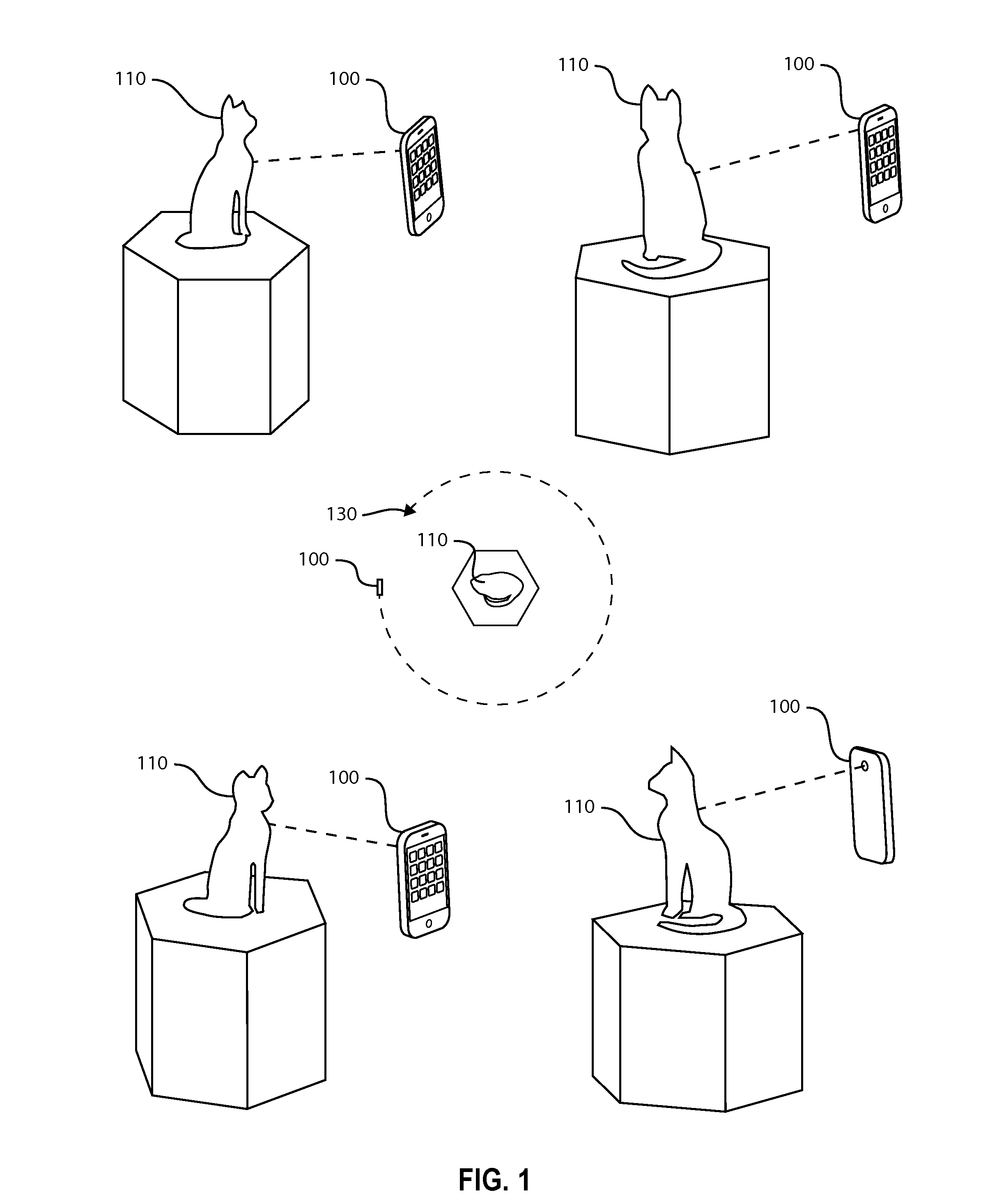
[0028]the 3D model capture device employs a smart phone with an auxiliary tool, an accessory to be attached to and used with the smart phone camera or integrated into a smart phone. The accessory contains a laser rangefinder and also uses the smart phone's inertial measurement unit (IMU) consisting of an accelerometer, gyroscope, and compass. In various versions, the IMU may be included in the accessory or it may be built into the smart phone. The laser rangefinder beam is aligned along or near the axis of the camera in a fixed and known position so that range measurements can be directly and accurately associated with the range from the camera to the rangefinder spot in the scene. The laser rangefinder provides an accurate range measurement with each image. Any laser distance measuring technology could be used including triangulation, phase-shift, time-of-flight, and interferometric. The essential characteristic of the distance measuring tool used in this embodiment is that the mea...

embodiment 100

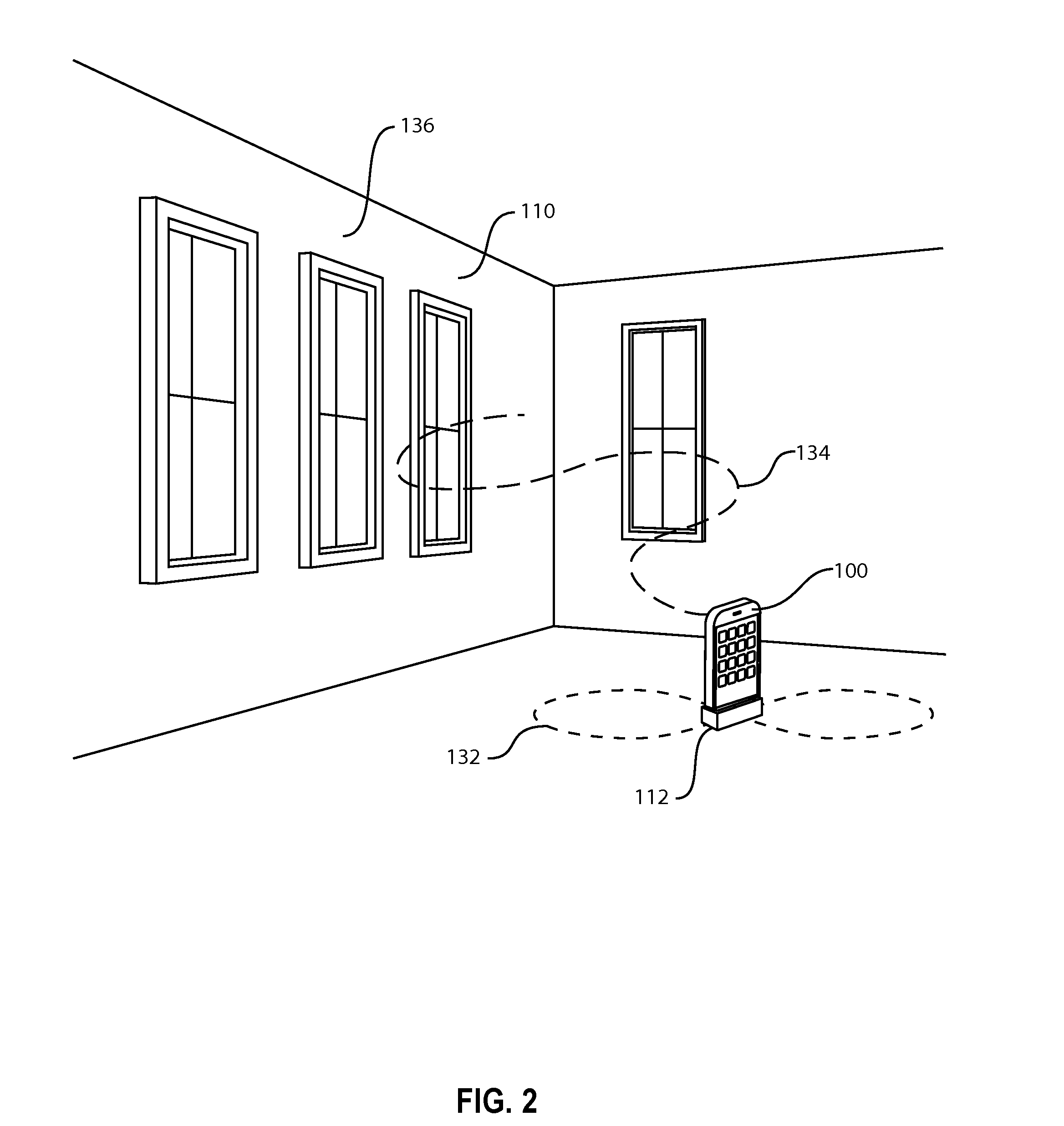
[0031]FIG. 2 illustrates the embodiment 100 of the 3D model capture system of FIG. 1 with a laser range finder 112 but the model to be captured is of a scene 111 or portions of the scene for measurement purposes. FIG. 2 illustrates a possible partial movement 132 of the camera (the figure-8 path) and the resultant path of the laser range finder 134 on surfaces 136 in the scene 111. The key concept illustrated is that the camera device is moved on a path such that the camera covers a range of positions as the image sequence is captured as opposed to remaining approximately stationary with just its orientation changed to capture images of the complete scene. Since SFM is based on triangulation, greater measurement accuracy is achieved by having a larger triangulation baseline. In the case illustrated in FIG. 2, this means that the 3D model accuracy of each point of interest in the scene is increased as the range of camera positions capturing the image of the points of interest is incr...


PUM


Abstract

Method and System for 3D capture based on SFM with simplified pose detection is disclosed. This invention provides a straightforward method to directly track the camera's motion (pose detection) thereby removing a substantial portion of the computing load needed to build the 3D model from a sequence of images.

Description

RELATED APPLICATION[0001]This application is a utility application claiming priority of U.S. provisional application(s) Ser. No. 61 / 732,636 filed on 3 Dec. 2012; Ser. No. 61 / 862,803 filed 6 Aug. 2013; and Ser. No. 61 / 903,177 filed 12 Nov. 2013 Ser. No. 61 / 948,401 filed on 5 Mar. 2014; U.S. Utility application Ser. No. 13 / 861,534 filed on 12 Apr. 2013; and Ser. No. 13 / 861,685 filed on 12 Apr. 2013; and Ser. No. 14 / 308,874 filed Jun. 19, 2014 and Ser. No. 14 / 452,937 filed 6 Aug. 2013; Ser. No. 14 / 539,924 filed 12 Nov. 2004.TECHNICAL FIELD OF THE INVENTION[0002]The present invention generally relates to optical systems, more specifically to electro-optical systems that are used to determine the camera orientation and position (collectively known as pose) and capture 3D models relative to the photographed scene in order to extract correct dimensions and positions of physical objects from photographic images.BACKGROUND OF THE INVENTION[0003]The task of capturing the 3D information in a s...

Claims


Application Information

Patent Timeline
Patent Type & Authority Applications(United States)
IPC IPC(8): G06T17/20G06T7/20G06T7/00H04N13/02H04N13/221
CPCG06T17/20H04N13/0203G06T2207/30244G06T7/0042G06T7/20G01B11/24G01S17/08G06T7/564G06T7/579H04N13/221H04N13/254H04N13/246G01S17/86
Inventor JOVANOVIC, DEJANBEARDMORE, KEITHMYLLYKOSKI, KARIGROTELUESCHEN, JAMES H.FREEMAN, MARK O.
Owner JOVANOVIC DEJAN
Why Eureka
Try Eureka