Wearable electronic device

a wearable electronic device and wearable technology, applied in the field of wearable electronic devices, can solve the problems of reducing user's willingness to use and acceptance, difficult for the external appearance of the wearable electronic device to be similar to that of a traditional watch, and affecting the use of the wearable electronic device. achieve the effect of good antenna radiation efficiency and metal appearan

Inactive Publication Date: 2016-09-08
ACER INC
View PDF19 Cites 30 Cited by
  • Summary
  • Abstract
  • Description
  • Claims
  • Application Information

AI Technical Summary

Benefits of technology

[0009]Based on the above, the wearable electronic device of the invention adopts a metal ring-shaped frame providing a metal appearance, and is arranged with a conductive film, a grounding element and a signal element, wherein the conductive film and the metal ring-shaped frame are spaced apart by a predetermined gap to make the predetermined gap to constitute a resonance cavity, and the grounding element is coupled to the metal ring-shaped frame and the conductive film. And, the signal element is coupled to the metal ring-shaped frame, and forms a close

Problems solved by technology

However, when the wearable electronic device is arranged with an antenna used for transmitting or receiving a wireless signal, a metal material frame will act as a shield to a wireless signal of the antenna and is not advantageous for obtaining good antenna radiation efficiency and causes the signal receiving results of the wearable electro

Method used


Image

  • Wearable electronic device
  • Wearable electronic device
  • Wearable electronic device

Examples


Embodiment Construction

[0015]Reference will now be made in detail to the present preferred embodiments of the invention, examples of which are illustrated in the accompanying drawings. Wherever possible, the same reference numbers are used in the drawings and the description to refer to the same or like parts.

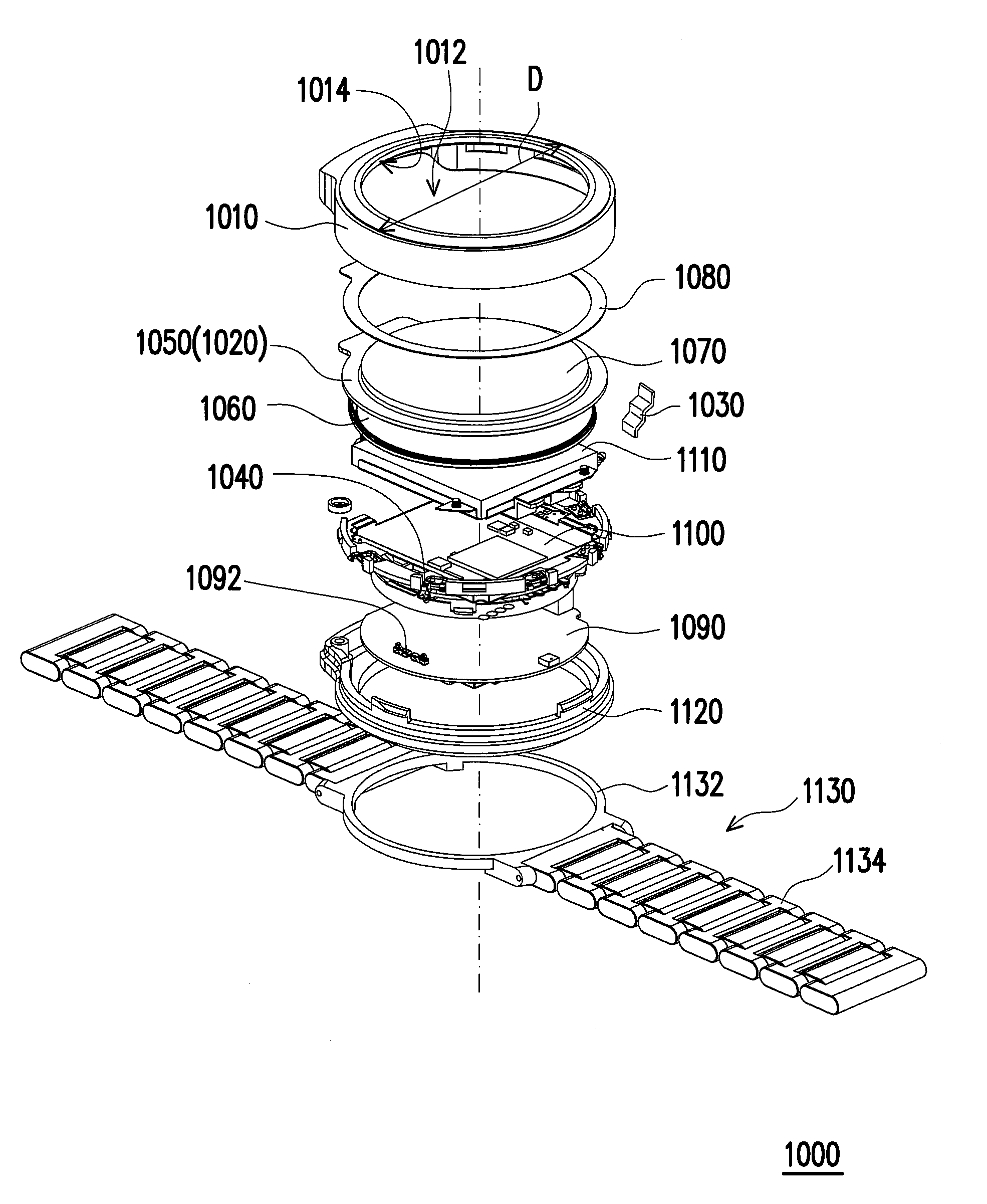
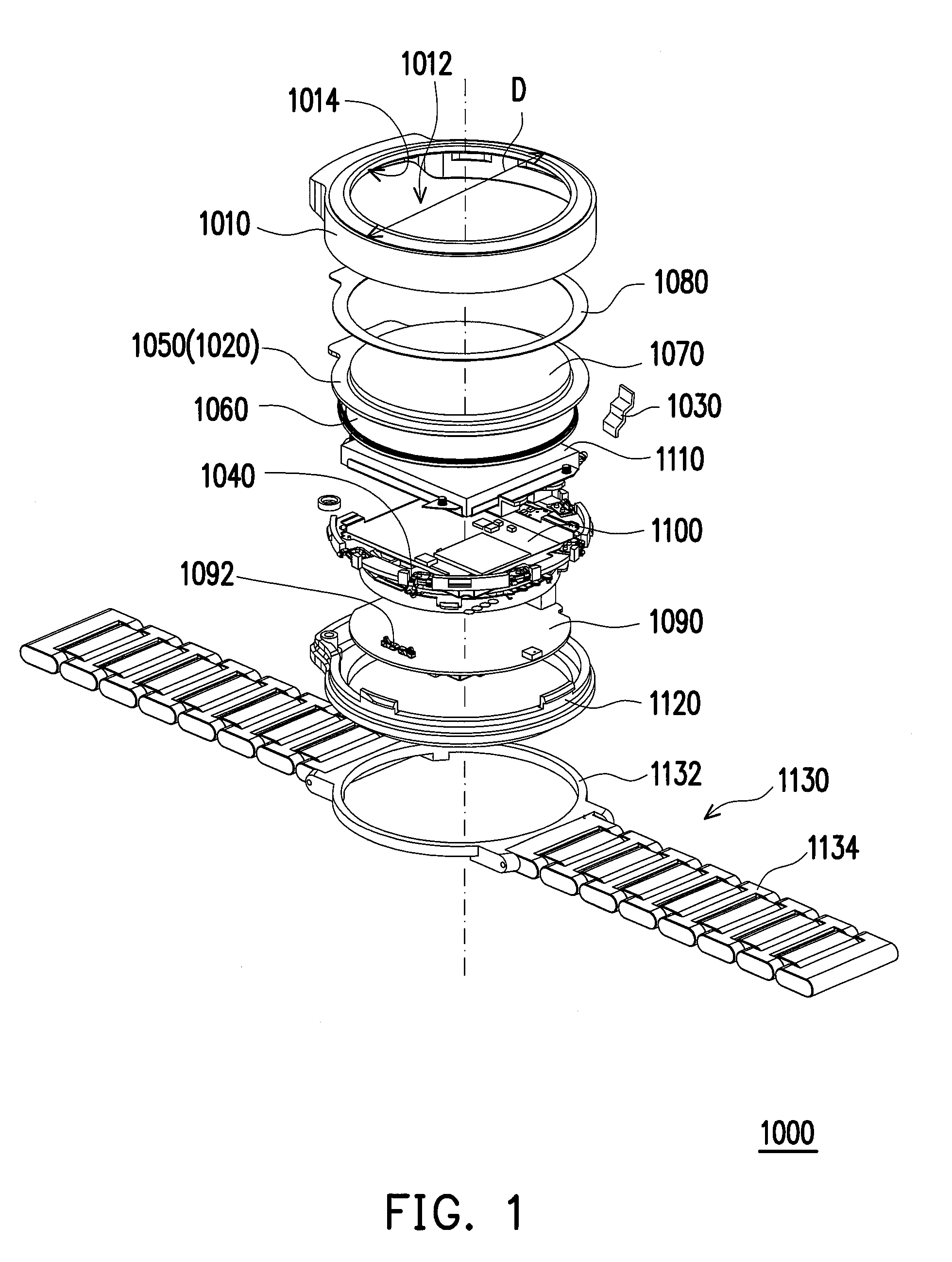
[0016]FIG. 1 is an exploded schematic diagram of a wearable electronic device according to an embodiment of the invention. In the present embodiment, a wearable electronic device 1000, for example, is a smart watch or other suitable electronic device which may be worn on a body of a user, for example, worn on the wrist of a user; however the type of the wearable electronic device 1000 should not be construed as a limitation to the invention. The wearable electronic device 1000 includes a metal ring-shaped frame 1010, a conductive film 1020, a grounding element 1030 and a signal element 1040. The conductive film 1020 is arranged in the metal ring-shaped frame 1010, and the conductive film 1020 and the...


PUM


Abstract

A wearable electronic device including a metal ring-shaped frame, a conductive film, a grounding element and a signal element is provided. The conductive film is arranged in the metal ring-shaped frame, and the conductive film and the metal ring-shaped frame are spaced apart by a predetermined gap to constitute a resonant cavity. The grounding element is arranged in the metal ring-shaped frame and coupled with the metal ring-shaped frame and the conductive film. The signal element is arranged in the metal ring-shaped frame and coupled between the metal ring-shaped frame and a circuit board. The signal element and grounding element constitute a closed resonant cavity with a specific length therebetween for serving as an antenna of the wearable electronic device.

Description

CROSS-REFERENCE TO RELATED APPLICATION[0001]This application claims the priority benefit of Taiwan application serial no. 104107011, filed on Mar. 5, 2015. The entirety of the above-mentioned patent application is hereby incorporated by reference herein and made a part of this specification.BACKGROUND OF THE INVENTION[0002]1. Field of the Invention[0003]The invention relates to an electronic device, and relates particularly to a wearable electronic device.[0004]2. Description of Related Art[0005]In recent years, along with advances of miniaturization in industrial technology and a rise in health awareness, a wearable electronic device such as a smart watch has been developed gradually and the technology is maturing. A design of a wearable electronic device requires consideration in two fields: portable convenience and product appearance similar to a traditional watch. In other words, in the pursuit of portable convenience (design towards small and thin dimensional) of the wearable e...

Claims


Application Information

Patent Timeline
IPC IPC(8): H01Q1/27G06F3/041
CPCG06F3/0412H01Q1/273H01Q1/44H01Q13/18G06F3/041G04G21/04G04R60/12G04G9/00
Inventor CHANG, YU-CHIALIN, HSIEH-CHIHCHIU, PEI-YUANLIN, HSIEN-CHANG
Owner ACER INC
Why Eureka
Try Eureka