Cellular phone

a cellular phone and antenna technology, applied in the field of portable devices, to achieve the effect of improving antenna radiation efficiency and without adversely affecting antenna characteristics and device characteristics

Inactive Publication Date: 2012-06-12
LENOVO INNOVATIONS LTD HONG KONG
View PDF14 Cites 0 Cited by
  • Summary
  • Abstract
  • Description
  • Claims
  • Application Information

AI Technical Summary

Benefits of technology

[0020]One way of improving the above problems is to place the electromagnetic field control plate by effectively utilizing the space in the hinge assembly. An example of such placement is shown in FIGS. 5(a) and 5(b). FIG. 5(a) shows a folded state, and FIG. 5(b) an unfolded state. As shown in FIG. 5(b), electromagnetic field control plate 14 which is highly flexible is disposed so as to extend in upper and lower casings 2, 3 through hinge assembly 4. Electromagnetic field control plate 14 has an upper portion fixed to a flat region of an inner wall surface of upper casing 2, and a lower portion fixed to a flat region of an inner wall surface of lower casing 3. In addition, electromagnetic field control plate 14 has a central portion extending along an inner circumferential surface of hinge assembly 4, but not fixed so that its shape can be changed relatively freely.
[0029]It is an object of the present invention to improve antenna radiation efficiency without preventing an upper casing and a lower casing from being opened and closed and also without adversely affecting antenna characteristics and device characteristics.

Problems solved by technology

Many cellular phones available recently are of the foldable type, with an antenna being often installed near the hinge assembly due to packaging space limitations.

Method used


Image

  • Cellular phone
  • Cellular phone
  • Cellular phone

Examples


exemplary embodiment 1

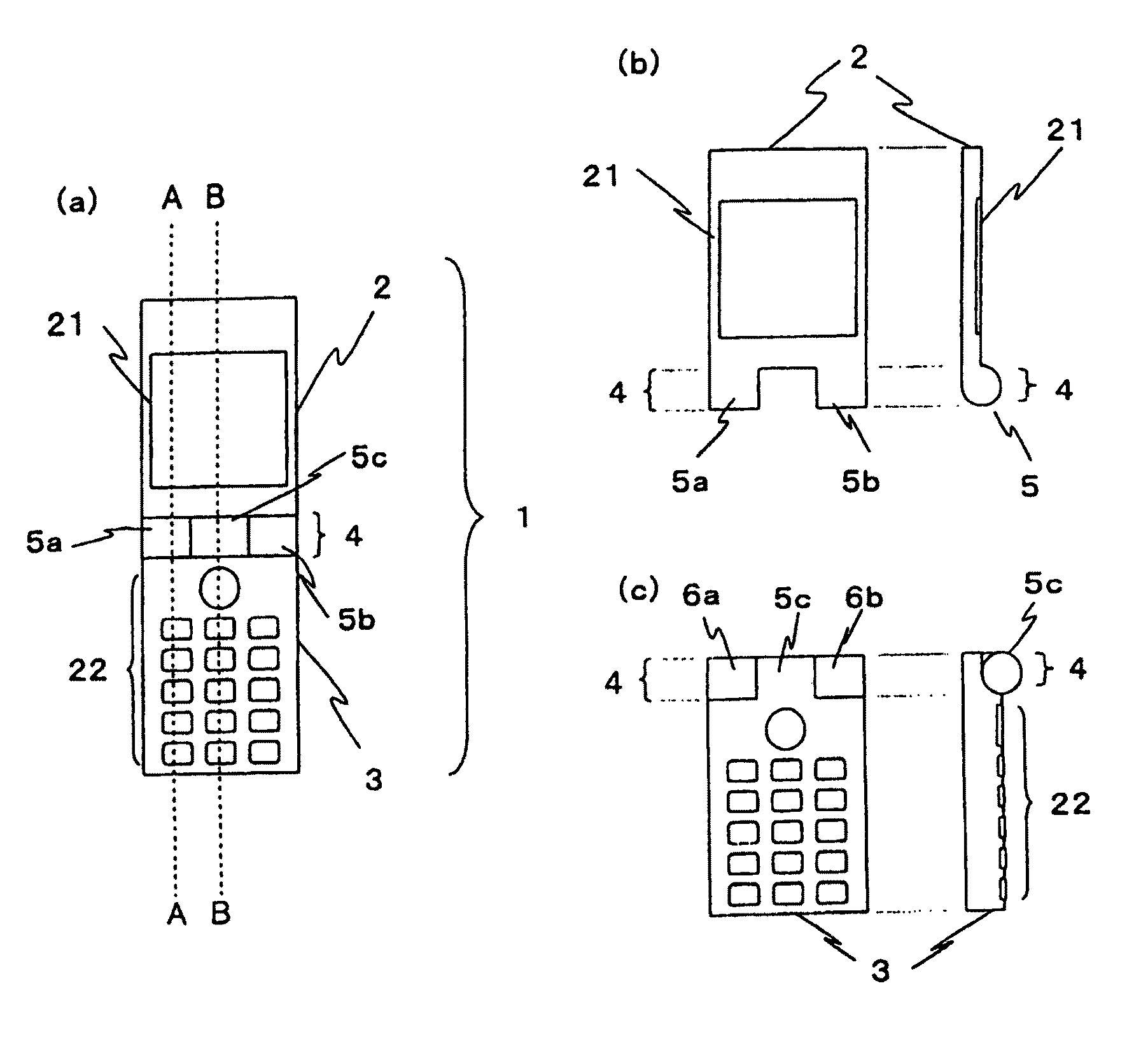
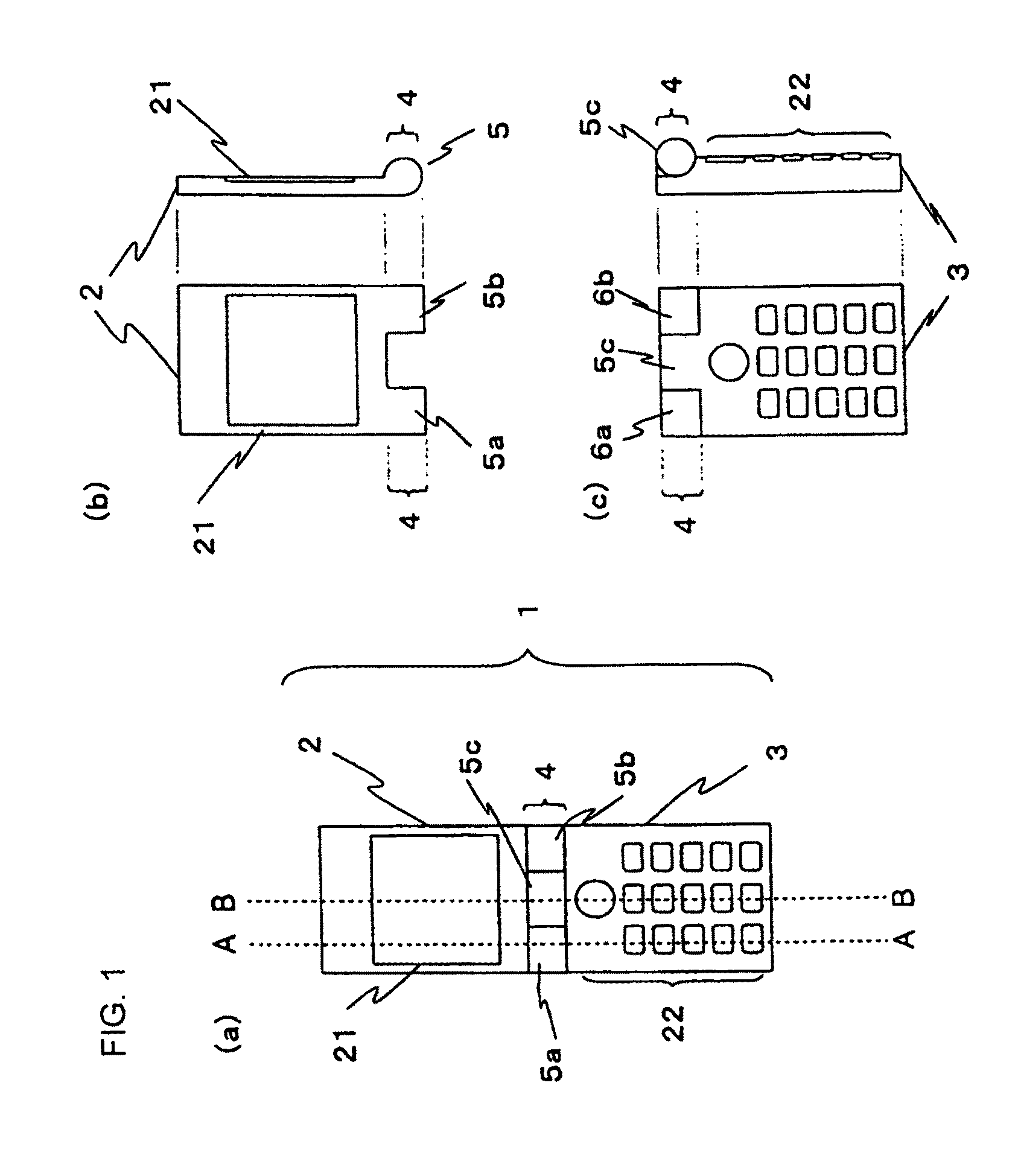
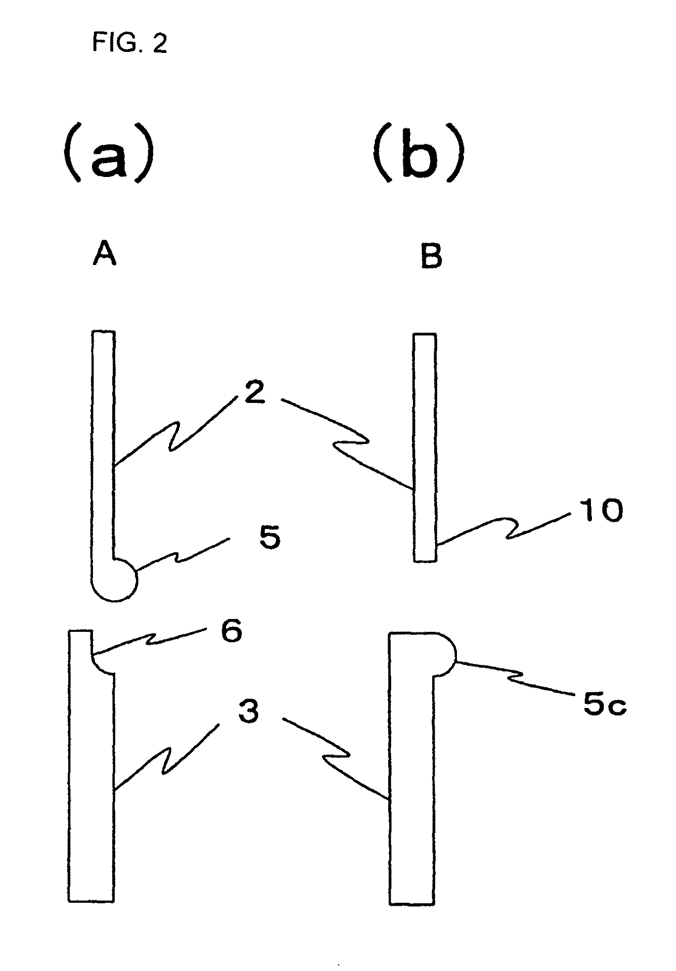
[0063]A cellular phone according to an exemplary embodiment of the present invention will be described in detail below with reference to the drawings. FIG. 7 is a schematic front elevational view of cellular phone 1 according to the present exemplary embodiment. Cellular phone 1 comprises a first casing (upper casing 2) and a second casing (lower casing 3) which are openably and closably coupled to each other by hinge assembly 4. FIG. 8(a) is an exploded perspective view showing the basic structure of upper casing 2, and FIG. 8(b) is an exploded perspective view showing the basic structure of lower casing 3. FIG. 9 shows upper casing 2 and lower casing 3 which are separate from each other for illustrative purposes. In the description which follows, the upper casing and the lower casing may also collectively be referred to as “upper and lower casings”. FIG. 9(a) is a front elevational view showing front surfaces of upper and lower casings 2, 3. FIG. 9(b) is a cross-sectional view tak...

exemplary embodiment 2

[0085]A cellular phone according to another exemplary embodiment of the present invention will be described below. The cellular phone according to the present exemplary embodiment has basic structure that is identical to the cellular phone according to exemplary embodiment 1. Therefore, identical structural details will not be described below.

[0086]FIG. 12(a) is an exploded perspective view of upper casing 2 of the cellular phone according to the present exemplary embodiment, and FIG. 12(b) is an exploded perspective view of lower casing 3 thereof. FIG. 13(a) shows a first control plate disposed in upper casing 2, and FIG. 13(b) shows a second control plate disposed in lower casing 2. First control plate 10 corresponds to a first reflective member according to the present invention. Second control plate 11 corresponds to a second reflective member according to the present invention. In these figures and figures to be referred to below which show upper and lower casings 2, 3, the LCD...

exemplary embodiment 3

[0104]A cellular phone according to still another exemplary embodiment of the present invention will be described below. FIG. 23(a) is an exploded perspective view of upper casing 2 of the cellular phone according to the present exemplary embodiment, and FIG. 23(b) is an exploded perspective view of lower casing 3 thereof.

[0105]As shown in FIGS. 23(a) and 23(b), half hinges 5a, 5b, 5c of upper casing 2 and lower casing 3 of the cellular phone according to the present exemplary embodiment are positionally inverted. Specifically, half hinge 5a is disposed centrally on the lower end of upper casing 2, and half hinges 5b, 5c are disposed respectively on left and right ends of the upper end of the lower casing.

[0106]Table 1 shows the casing structures according to the exemplary embodiments which are tabulated in relation to the half hinges. It can be understood from Table 1 that the casings of the cellular phone according to the present exemplary embodiment are different from those accor...


PUM


Abstract

A cellular phone includes upper casing 2 having a front surface with LCD panel 21 disposed thereon, lower casing 3 having a front surface with key pad 22 disposed thereon, and an antenna, upper and lower casings 2, 3 being openably and closably coupled to each other. First control plate 10 for reflecting electromagnetic waves is disposed in upper casing 2, and second control panel 11 for reflecting electromagnetic waves is disposed in lower casing 3. First control plate 10 and second control plate 11 comprise separate members which are independent of each other. When the cellular phone is in an unfolded state in which the angle formed between the front surface of upper casing 2 and the front surface of the lower casing 3 is maximum, first control plate 10 and second control plate 11 have a maximum projected area on the surfaces of upper and lower casings 2, 3.

Description

TECHNICAL FIELD[0001]The present invention relates to a portable device for sending and receiving radio waves, and more particularly to a cellular phone.BACKGROUND ART[0002]The basic structure of a general cellular phone will be described below. FIG. 1 is a set of schematic views showing the basic structure of foldable cellular phone 1. Specifically, FIG. 1(a) is a front elevational view of foldable cellular phone 1. FIG. 1(b) is a set of a front elevational view and a side elevational view of upper casing 2. FIG. 1(c) is a set of a front elevational view and a side elevational view of lower casing 3.[0003]As shown in FIG. 1(a), cellular phone 1 comprises upper casing 2 positioned upwardly of hinge 4 and lower casing 3 positioned downwardly of hinge 4. Upper casing 2 and lower casing 3 have hollow box shapes, respectively. Upper casing 2 and lower casing 3 are often made of a nonmetallic material such as resin, plastic, or the like.[0004]LCD panel 21 serving as a display means, a sp...

Claims


Application Information

Patent Timeline
Patent Type & Authority Patents(United States)
IPC IPC(8): H04M1/00
CPCH01Q1/243H01Q19/185H04M1/0212H04M1/0216
Inventor HANKUI, EIJIYOKOYAMA, YUKIONAKAMURA, SHINYAKOJIMA, TAKUYA
Owner LENOVO INNOVATIONS LTD HONG KONG
Why Eureka
Try Eureka