Piezoelectric vibrating piece and piezoelectric vibrator

a piezoelectric and vibrating piece technology, applied in the direction of piezoelectric/electrostrictive/magnetostrictive devices, electric windings, instruments, etc., can solve the problems of difficulty in sufficiently decreasing a ci value, and the inability to obtain desired vibration characteristics, etc., to achieve the effect of reducing a size and an oscillation frequency

Active Publication Date: 2016-09-15
SII CRYSTAL TECH
View PDF8 Cites 4 Cited by
  • Summary
  • Abstract
  • Description
  • Claims
  • Application Information

AI Technical Summary

Benefits of technology

[0026]According to the present invention, it is possible to achieve reductions in a size and an oscillation frequency.
[0027]According to the present invention, even when a reduction in size is pursued, it is possible to reduce a CI value to equal to or less than 80 kΩ and to reduce an oscillation frequency to equal to or less than 40 kΩ.

Problems solved by technology

When the piezoelectric vibrating piece is made small, there is a tendency for a crystal impedance (hereinafter, referred to as a “CI value”) of the piezoelectric vibrating piece to be increased, which results in a concern in that desired vibration characteristics cannot be obtained.
However, when a reduction in the size of a piezoelectric vibrating piece is pursued, there is a limitation in forming the wide hammer portion in terms of a space, which results in a difficulty in sufficiently decreasing a CI value.

Method used


Image

  • Piezoelectric vibrating piece and piezoelectric vibrator
  • Piezoelectric vibrating piece and piezoelectric vibrator
  • Piezoelectric vibrating piece and piezoelectric vibrator

Examples


first embodiment

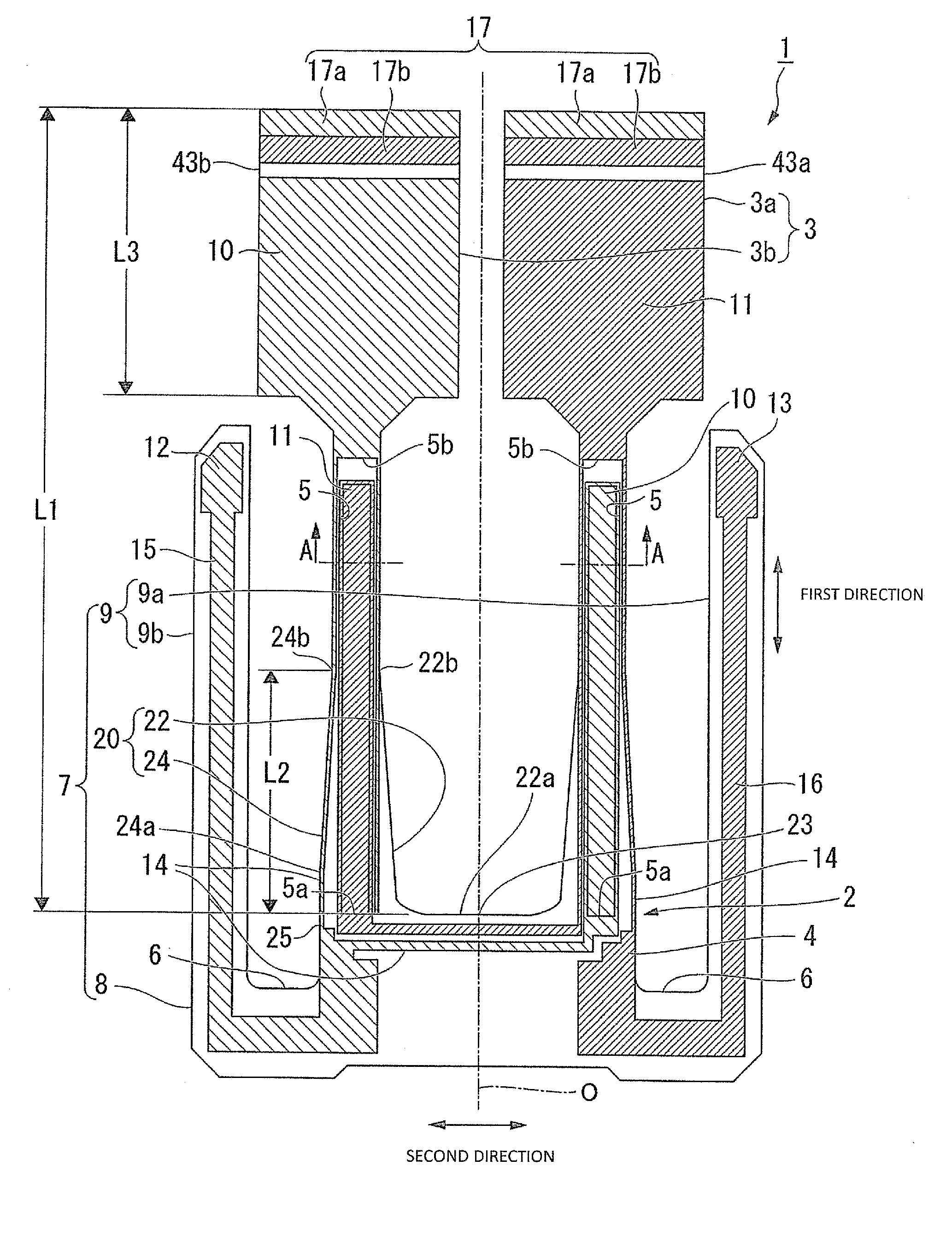
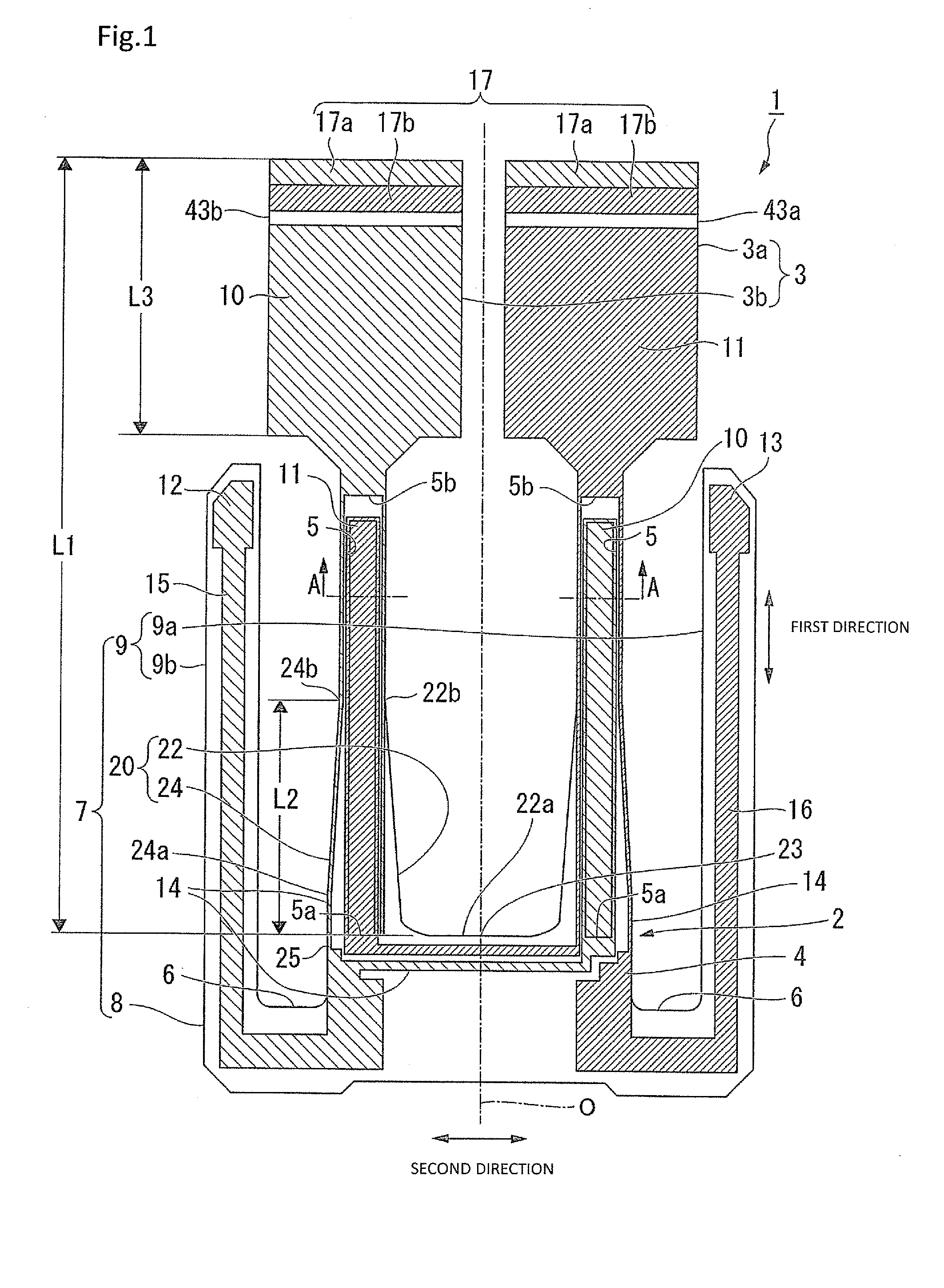
[0038]FIG. 1 is a plan view of a surface side of a piezoelectric vibrating piece 1. In the present embodiment, a description will be given by taking a tuning fork type piezoelectric vibrating piece which is a type with a groove portion as an example of a piezoelectric vibrating piece 1.

[0039]As illustrated in FIG. 1, the piezoelectric vibrating piece 1 includes a tuning fork type piezoelectric plate 2 formed of a piezoelectric material such as quartz crystal, lithium tantalite, or lithium niobate.

[0040]The piezoelectric plate 2 includes a vibrating portion 3 which is formed so as to extend along a direction (hereinafter, referred to as a “first direction”) which is parallel to a center axis O, and a base portion 4 that supports a base end of the vibrating portion 3. The vibrating portion 3 includes a pair of vibrating arm portions 3a and 3b that are disposed lined up in a direction (hereinafter, referred to as a “second direction”) which is perpendicular to the center axis O.

[0041]T...

first modification example of first embodiment

[0086]Next, a piezoelectric vibrating piece 1B according to a first modification example of the first embodiment will be described.

[0087]FIG. 6 is a plan view illustrating a configuration on a surface side of the piezoelectric vibrating piece 1B according to the first modification example of the first embodiment. Meanwhile, in the following description, components in common with those in the above-described configuration will be denoted by the same reference numerals and signs, and a description thereof will be omitted here. Excitation electrodes 10 and 11, mounting electrodes 12 and 13, and the like have the same configurations as those in the above-described embodiment, and thus are not shown in the drawing.

[0088]In the piezoelectric vibrating piece 1B according to the first modification example, a supporting arm portion 9B is formed on an end face 23 of a base portion 4B on the distal end side between a pair of vibrating arm portions 3a and 3b. The piezoelectric vibrating piece 1...

second modification example of first embodiment

[0091]Next, a piezoelectric vibrating piece 1C according to a second modification example of the first embodiment will be described.

[0092]FIG. 7 is a plan view illustrating a configuration on a surface side of the piezoelectric vibrating piece 1C according to the second modification example of the first embodiment.

[0093]The piezoelectric vibrating piece 1C according to the second modification example is formed to have a quadrangular plate shape in which a base portion 4C includes a pair of end faces 25 in the second direction, an end face 23 of the base portion 4C on the distal end side, and an end face 28 of the base portion 4C on the rear end side at four side portions thereof. The base portion 4C is provided with a mounting electrode (not shown in FIG. 7) which is electrically connected to the outside.

[0094]According to the piezoelectric vibrating piece 1C, it is possible to mount the piezoelectric vibrating piece on, for example, a package through the base portion 4C. In the pie...


PUM


Abstract

A pair of vibrating arm portions are disposed lined up in a second direction perpendicular to a first direction and are configured such that base end sides thereof in the first direction are fixed to a base portion. A pair of inclined surfaces are formed on both sides in the second direction on the base end side of the vibrating arm portion so that a width of the vibrating arm portion in the second direction is gradually widened from the distal end side to the base end side. A length of a region, having the pair of inclined surfaces formed therein, in the first direction is set to equal to or greater than 0.25 times and equal to or less than 0.5 times of a total length of the vibrating arm portion from the base end to the distal end.

Description

RELATED APPLICATIONS[0001]This application claims priority under 35 U.S.C. §119 to Japanese Patent Application No. 2015-049779 filed on Mar. 12, 2015, the entire content of which is hereby incorporated by reference.BACKGROUND OF THE INVENTION[0002]1. Field of the Invention[0003]The present invention relates to a piezoelectric vibrating piece and a piezoelectric vibrator.[0004]2. Background Art[0005]Piezoelectric vibrators using quartz crystal or the like as a time source, a timing source of a control signal, a reference signal source, or the like have been used in mobile phones and portable information terminal devices. As one of such types of piezoelectric vibrators, a piezoelectric vibrator accommodating a piezoelectric vibrating piece within a vacuum-sealed cavity has been known. According to the piezoelectric vibrator, it is possible to vibrate a vibrating arm portion by a predetermined resonance frequency by applying a voltage to an excitation electrode formed in the vibrating ...

Claims


Application Information

Patent Timeline
Patent Type & Authority Applications(United States)
IPC IPC(8): H03H9/21H01L41/053G04C3/12
CPCH03H9/21H01L41/053G04C3/12H03H9/215H03H9/1014
Inventor KOBAYASHI, TAKASHIICHIMURA, NAOYA
Owner SII CRYSTAL TECH
Why Eureka
Try Eureka