
Heating-wire fastening base, a heating-wire fastener and a heating-wire fastening assembly

Inactive Publication Date: 2016-09-15
NANJING YIQING MACHINERY MANUFACTURING CO LTD
View PDF6 Cites 0 Cited by
  • Summary
  • Abstract
  • Description
  • Claims
  • Application Information

AI Technical Summary

Benefits of technology

The invention has several benefits, including easy assembly and disassembly, resistance to damage, simple construction, and low cost of production. Additionally, the metal structure at both ends of the fastening base improves the service life of the heating-wire, leading to better economic benefits.

Problems solved by technology

The installation of such heating-wire fastening device is relatively complicated, and the whole fastening bolt 5 should be removed when the heating-wire fastening device is disassembled, which causes inconvenient use of the fastener.

Method used


Image

  • Heating-wire fastening base, a heating-wire fastener and a heating-wire fastening assembly
  • Heating-wire fastening base, a heating-wire fastener and a heating-wire fastening assembly
  • Heating-wire fastening base, a heating-wire fastener and a heating-wire fastening assembly

Examples


Embodiment Construction

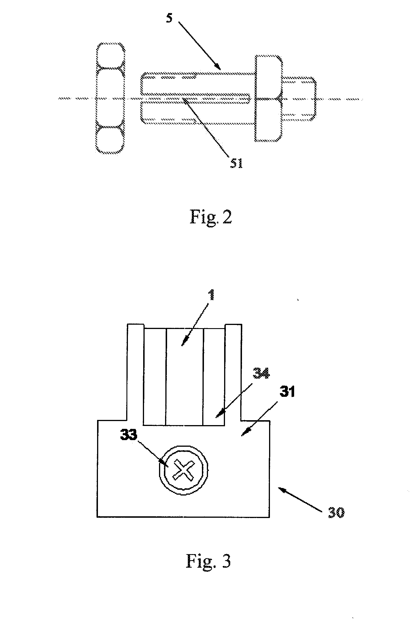
[0027]As shown in FIGS. 3 and 4, a heating-wire fastening device 30 according to an embodiment of the present invention comprises a fastening base 31 in which a heating-wire fastening groove 34 is formed at an approximately vertical direction. The heating-wire fastening groove 34 is a through groove of slot type, with its lower end bending in the fastening direction in which a fastener 33 moves within a fastening hole 32 so that the heating-wire is easy to be straightened and fastened. A fastening hole 32 is formed in a approximately transversal direction of the heating-wire fastening groove 34 and is communicated with the slant lower end of the heating-wire fastening groove 34. By arranging the direction of the fastening groove 34 and the direction of the fastening hole 32 (direction of fastening) in such a manner as mentioned above, the fastening hole 32 and the fastener 33 are assembled together so as to fasten the heating-wire within the heating-wire fastening groove 34. The abo...


PUM


Abstract

The present application discloses a heating-wire fastening base, a heating-wire fastening device and a heating-wire fastening assembly. The fastening base is provided with a heating-wire fastening groove at a first direction, and a fastening hole provided on the fastening base along a second direction which is unparallel with the first direction. The fastening hole is communicated with the heat-wire fastening groove. Thus, problems of difficult installation and lacking strength of assembly can be resolved, and advantageous effects are available, such as easy installation and disassembling, less time for operation, and low cost of manufacturing.

Description

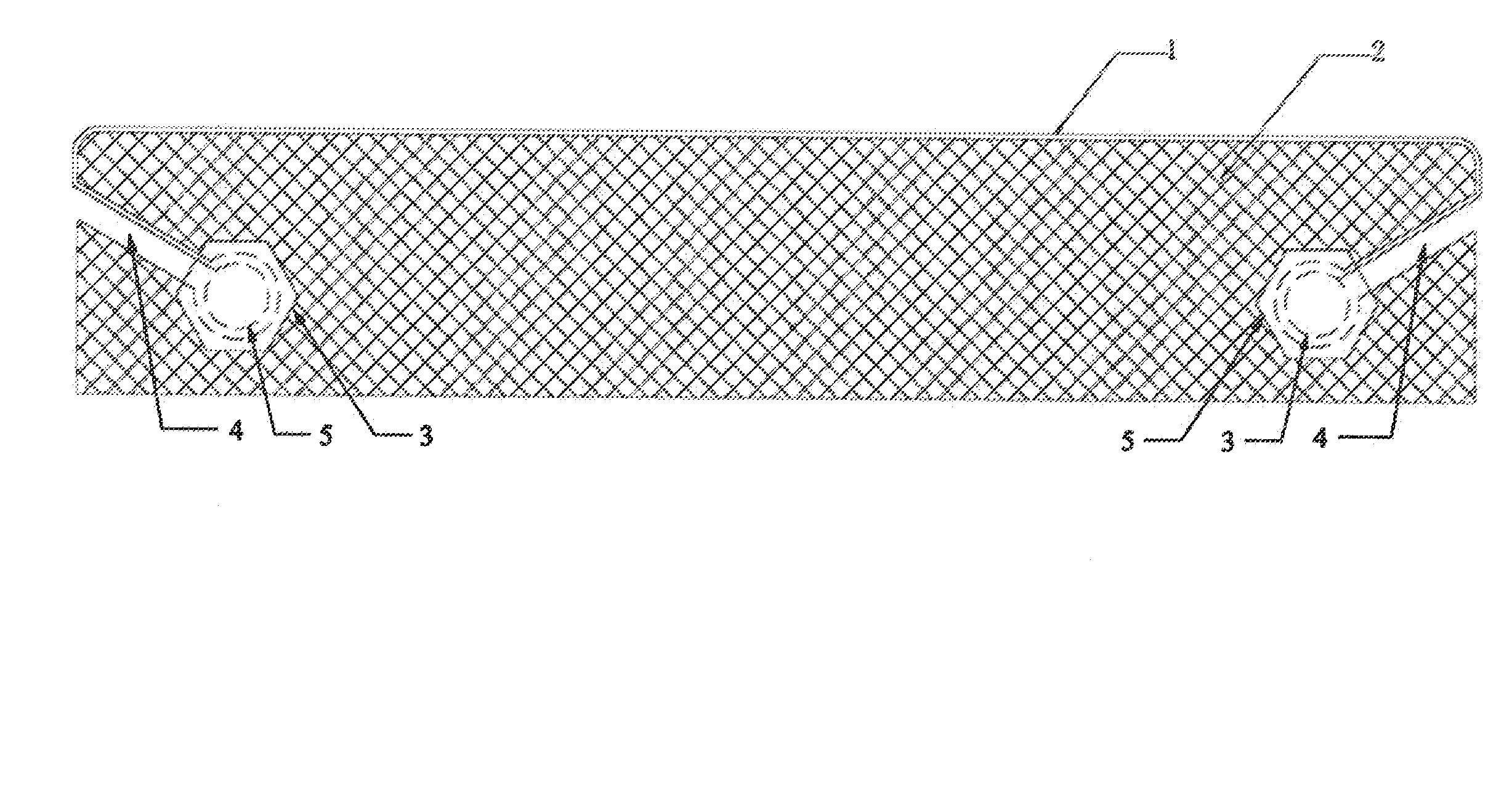
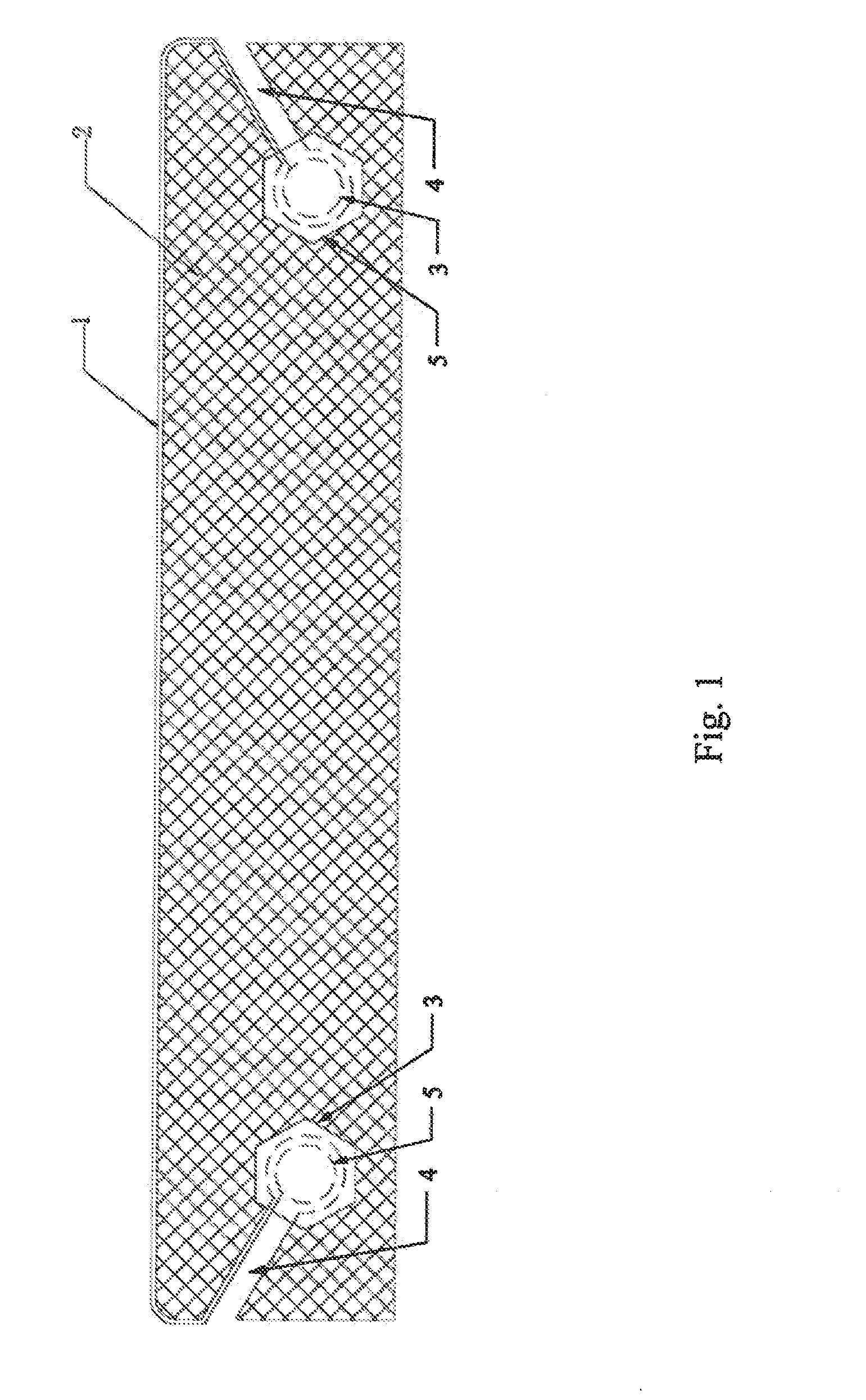
FIELD OF THE INVENTION[0001]The present application relates to the field of electrical heating, especially relating to a heating-wire fastening base, a heating-wire fastening device and a heating-wire fastening assembly.BACKGROUND OF THE INVENTION[0002]A heating-wire fastening device is a part often used at the sealing bar of a vacuum packaging machine. As shown in FIG. 1, most of the conventional fasteners comprise an epoxy resin board 2 with one through hole 3 being provided at each of the two ends thereof. A path 4 is provided between each of the through holes and corresponding one of the two ends of the epoxy resin board 2 for passing a heating-wire 1. A fastening bolt 5 is installed in the path 4 for fastening the heating-wire. The fastening bolt 4 is a conventional bolt with a groove 51 at the screw portion, as shown in FIG. 2. The heating-wire 1 is inserted into the groove 51 of the fastening bolt 5 during operation, passes through the path 4 of the epoxy resin board 2, and t...

Claims


Application Information

Patent Timeline
IPC IPC(8): H05B3/06H05B3/02
CPCH05B3/02H05B3/06B65B51/10B65B65/00
Inventor ZHANG, ZHENHAI
Owner NANJING YIQING MACHINERY MANUFACTURING CO LTD
Learn More