Locking Grip Orthopedic Implant Extraction Tool

a technology of orthopedic implants and grips, applied in the field of locking grip orthopedic implant extraction tools, can solve the problems of difficult removal, inability to adequately grasp or hold the implant, and generally not suitable for other types of implants to be removed

Active Publication Date: 2016-09-22
SHUKLA MEDICAL
View PDF2 Cites 15 Cited by
  • Summary
  • Abstract
  • Description
  • Claims
  • Application Information

AI Technical Summary

Benefits of technology

[0005]Accordingly, an object of the present invention is to provide a tool for temporarily and securely connecting a...

Problems solved by technology

When a joint implant needs to be replaced, the surgeon needs to remove it, and removal can be difficult because the implant is fixed to adjacent bone by bone cement and/or bone in-growth.
Current devices which allow the implant to be gripped so that force can be appli...

Method used


Image

  • Locking Grip Orthopedic Implant Extraction Tool
  • Locking Grip Orthopedic Implant Extraction Tool
  • Locking Grip Orthopedic Implant Extraction Tool

Examples


first embodiment

FIGS. 1 Through 4

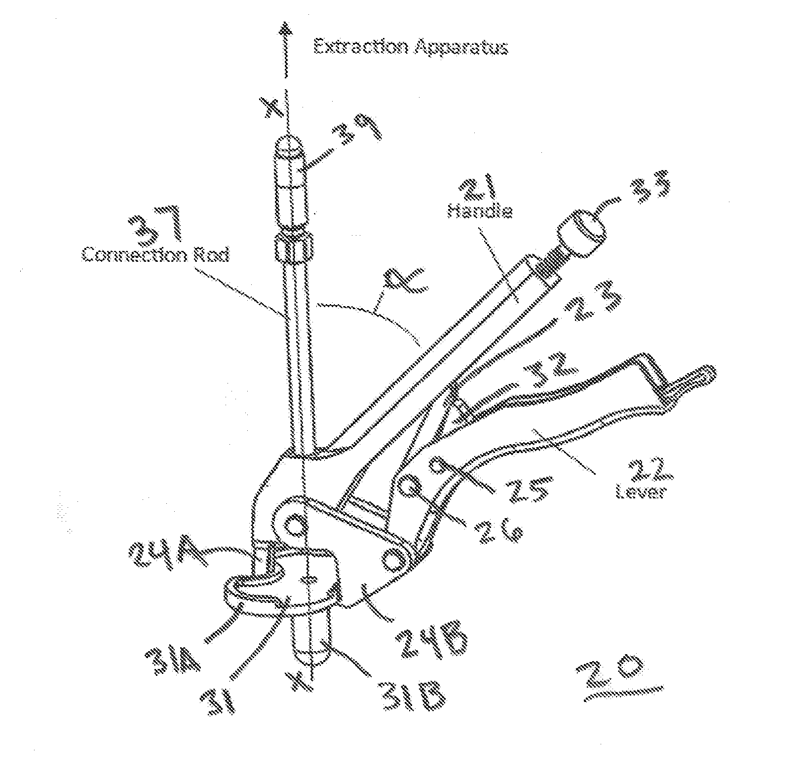
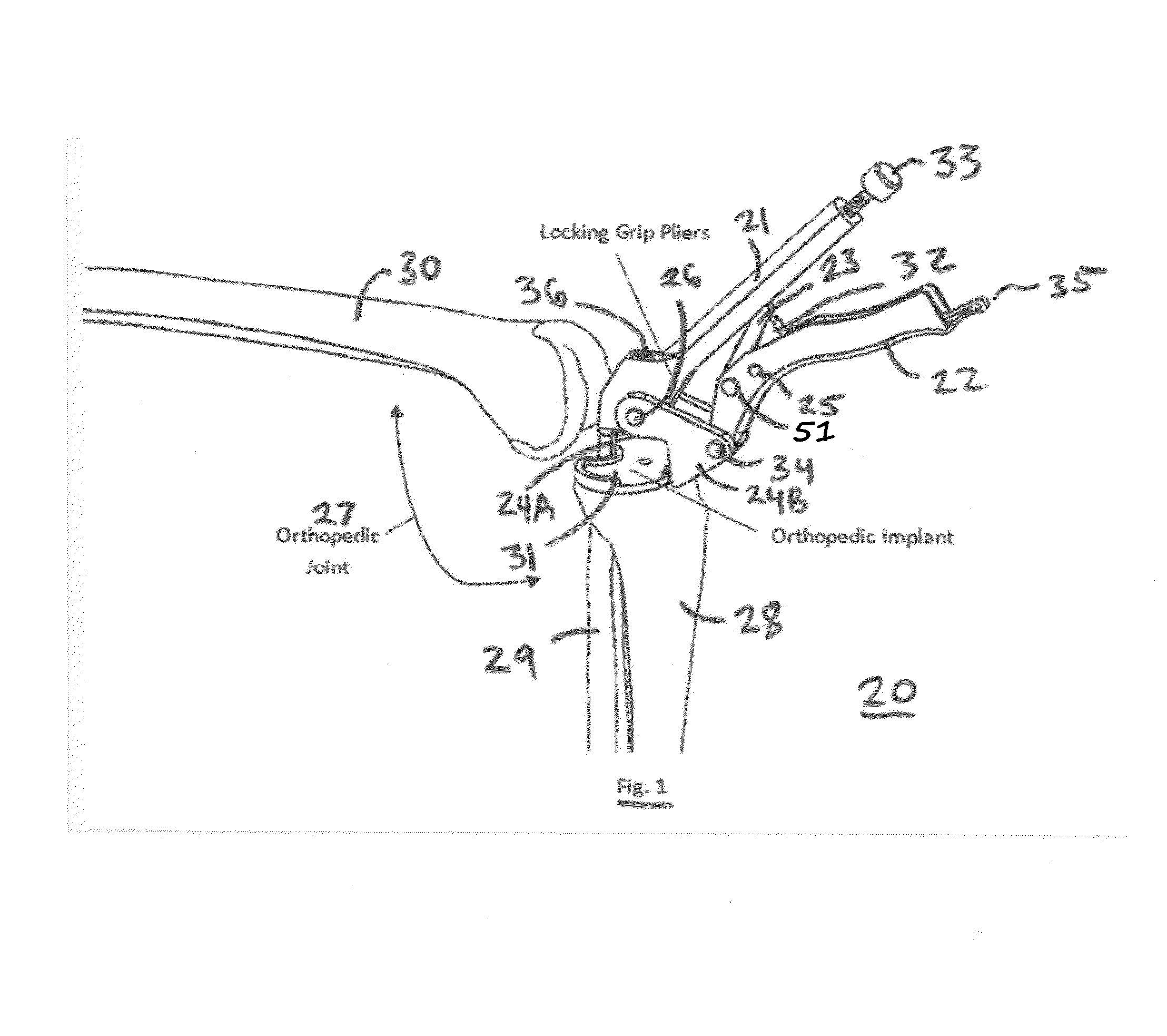
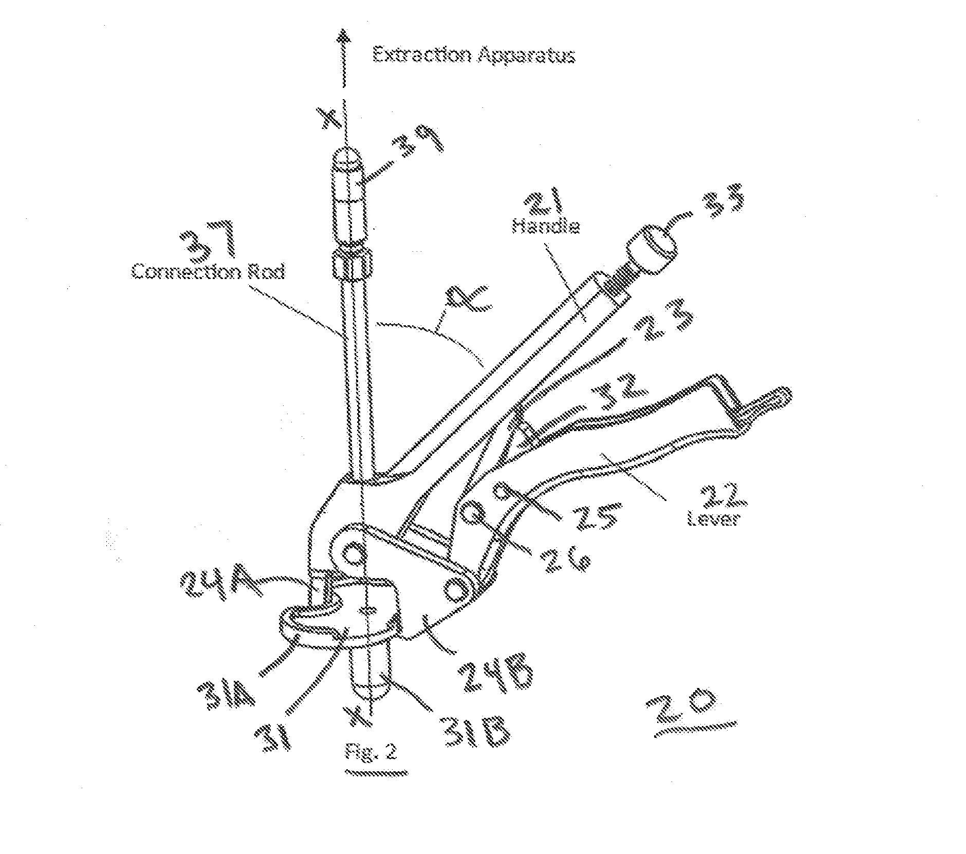
[0028]As shown FIGS. 1 to 4 the locking grip pliers tool 20 has an upper handle21 and a more massive lower or gripping handle 22 joined to the upper handle by a locking link 23 which cooperates with the handles to provide a locking grip mechanism. A first jaw 24A is affixed to an implant gripping end of the handle 21, while a second jaw 24B is pivotably mounted to the adjacent end of the gripping handle 22 for rotation about the pins 34 and 26.

[0029]The knee joint 27 includes the proximal ends of the tibia 28 and fibula 29, and the distal end of the femur 30. A metal orthopedic implant 31 has a base or tray 31A and a stem 31B which is embedded in the truncated proximal end of the tibia 28. The jaws 24A and 24B engage, and have sharp edges which extend below opposite sides of the implant tray 31A.

[0030]The locking link 23 has one end mounted for rotation about the pin 51 in the gripping handle 22, while the other end is T-shaped and slidably installed in a longitudin...

second embodiment

FIGS. 5 to 8D

[0046]In the second embodiment shown in FIGS. 5 through 8D, the tool 50 has the same construction as the tool 20 of FIGS. 1 to 4, except that the jaws are replaceable.

[0047]Over a period of time the jaws of the tool 20 can become damaged by the repetitive action of the jaws piercing under the implant, in and out of bone cement and / or bone, so that the jaws need to be replaced. Jaw damage can also occur if the surgeon mistakenly causes the jaws to be rammed into the sides of the implant tray as shown in FIG. 5. The mechanical advantage of the tool can result in so large a force being applied to the jaws that they are bent out of shape. In either of these scenarios, replacement of the jaws is more cost effective than replacement of the entire tool.

[0048]A change of jaws is sometimes needed when a different type of implant needs to be removed. Such an implant type may have “augments” in which the tray of the implant is relatively thick, requiring jaws with an extended reac...

third embodiment

FIGS. 9 Through 13

[0052]During the operation of the tools 20 and 40 they are subjected to vibration due to repetitive impact force applied by the slap hammer or other extraction device, causing the gripping handle to pop loose.

[0053]To prevent such inadvertent release of the handles from their locked position, in the third embodiment the tool 45 adds a sliding rod 46 and a C-shaped detent 47. The rod 46 is mounted so that it can slide in a direction transverse to the handles 21 and 22 and act as a secure locking mechanism which, when engaged, prevents movement of the link relative to the gripping handle and thus securely locks the tool in its closed position.

[0054]When the secure locking mechanism is engaged by sliding the rod 46 so that its larger diameter portion 48 is retained in the undercut portion of the C-shaped detent 47, the locking link cannot move relative to the gripping handle and the handles therefore cannot move relative to each other; thus keeping the jaws firmly cla...


PUM


Abstract

A locking grip extraction tool has plier handles with jaws having sharp beveled edges for moving in a direction so that an axis perpendicular to the plane of movement is oriented at an acute angle to the handles; the axis intersecting the plane of jaw movement at a point midway between the jaws. A locking link coupled to the handles is adapted to releasably lock the jaws onto an orthopedic implant. A connection rod can be threaded into a hole in one of the handles near the jaws, so that a force applying tool such as a slap hammer can be connected to the rod to apply force to remove the implant. The rod is in alignment with the axis, which alignment makes it easier to remove the implant.

Description

CROSS-REFERENCE TO RELATED APPLICATION[0001]This application claims the benefit of U.S. Provisional Application Ser. No. 62 / 135,793 filed Mar. 20, 2015 and entitled Locking Grip Orthopedic Implant Extraction Tool.BACKGROUND OF THE INVENTION[0002]The present invention relates to a tool for facilitating the removal of an orthopedic implant used in joint surgery.[0003]When a joint implant needs to be replaced, the surgeon needs to remove it, and removal can be difficult because the implant is fixed to adjacent bone by bone cement and / or bone in-growth.[0004]Current devices which allow the implant to be gripped so that force can be applied to remove it, don't adequately grasp or hold the implant, and tend to slip off or not optimally allow for application of removal force. While vise-grip pliers have been used to remove orthopedic pins, they are generally not suitable for removal of other types of implants.[0005]Accordingly, an object of the present invention is to provide a tool for te...

Claims


Application Information

Patent Timeline
IPC IPC(8): A61F2/46
CPCA61F2/461A61F2/4603A61F2002/4681A61F2002/4619A61F2002/4623A61F2002/4622A61F2002/30476A61F2002/30537
Inventor SWEITZER, ZACHARY ROBERT
Owner SHUKLA MEDICAL
Why Eureka
Try Eureka