Power generation system having compressor creating excess air flow and turbo-expander for supplemental generator

a power generation system and compressor technology, applied in steam engine plants, machines/engines, mechanical equipment, etc., can solve the problems of increasing power generation demand, increasing electric consumption, and reducing generator output, and achieve the effect of reducing excess air flow

Inactive Publication Date: 2016-09-22
GENERAL ELECTRIC CO
View PDF8 Cites 21 Cited by
  • Summary
  • Abstract
  • Description
  • Claims
  • Application Information

AI Technical Summary

Benefits of technology

[0006]A first aspect of the disclosure provides a power generation system, comprising: a gas turbine system including a turbine component, an integral compressor and a combustor to which air from the integral compressor and fuel are supplied, the combustor arranged to supply hot combustion gases to the turbine component, and the integral compressor having a flow capacity greater than an intake capacity of at least one of the combustor and the turbine component, creating an excess air flow; a turbo-expander powering a generator; and a first control valve controlling flow of the excess air flow along an excess air flow path to the turbo-expander.
[0007]A second aspect of the disclosure provides a power generation system, comprising: a gas turbine system including a turbine compon...

Problems solved by technology

The ability to increase power output on demand and/or maintain power output under challenging environmental settings is a continuous challenge in the industry.
For example, on hot days, the electric consumption is increased, thus increasing power generation demand.
Another challenge of hot days is that as temperature increases, compressor flow decreases, which results in decreased generator output.
This particular approach, however, typically requires a separate power source for the storage ve...

Method used


Image

  • Power generation system having compressor creating excess air flow and turbo-expander for supplemental generator
  • Power generation system having compressor creating excess air flow and turbo-expander for supplemental generator
  • Power generation system having compressor creating excess air flow and turbo-expander for supplemental generator

Examples


Embodiment Construction

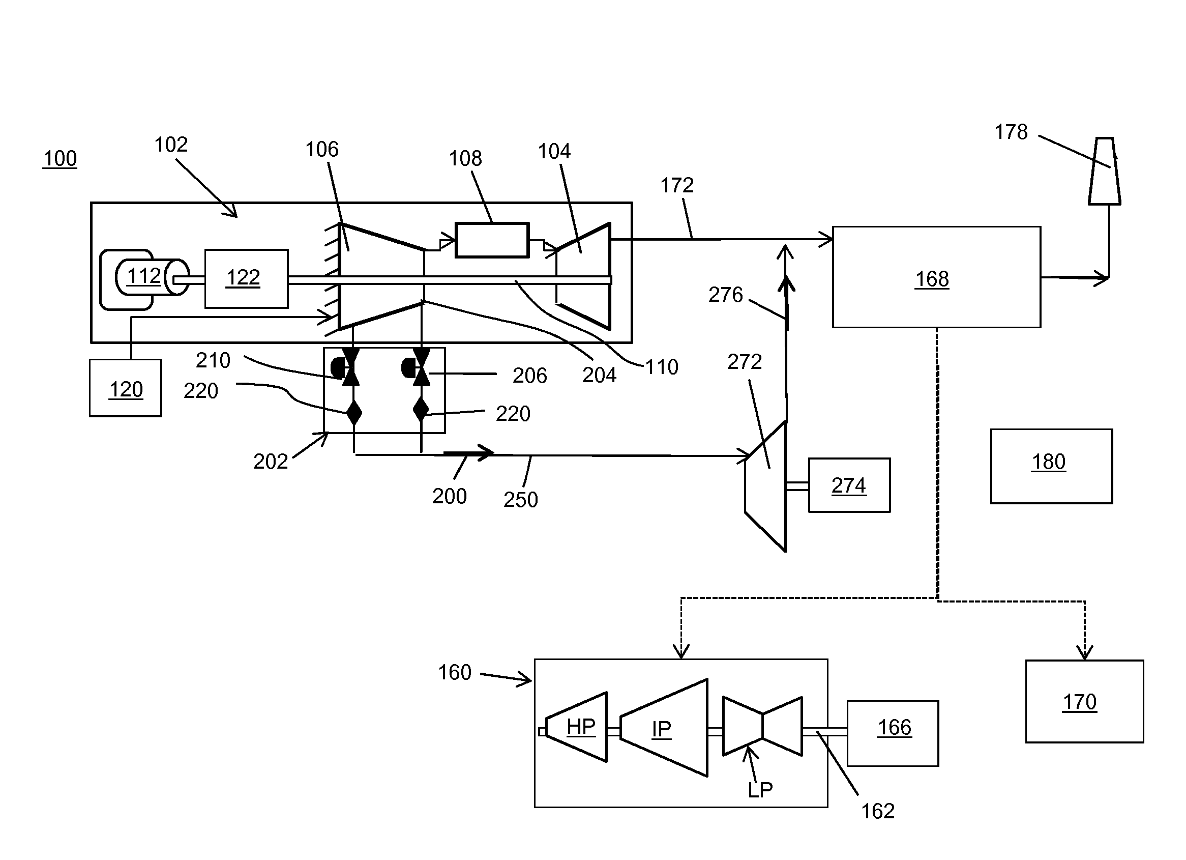
[0014]As indicated above, the disclosure provides a power generation system including a gas turbine system including a compressor that creates an excess air flow. Embodiments of the invention provide ways to employ the excess air flow to improve output and value of the power generation system.

[0015]Referring to FIG. 1, a schematic diagram of a power generation system 100 according to embodiments of the invention is provided. System 100 includes a gas turbine system 102. Gas turbine system 102 may include, among other components, a turbine component 104, an integral compressor 106 and a combustor 108. As used herein, “integral” compressor 106 is so termed as compressor 106 and turbine component 104 may be integrally coupled together by, inter alia, a common compressor / turbine rotating shaft 110 (sometimes referred to as rotor 110). This structure is in contrast to many compressors that are separately powered, and not integral with turbine component 104.

[0016]Combustor 108 may include...


PUM


Abstract

A power generation system may include a gas turbine system including a turbine component, an integral compressor and a combustor to which air from the integral compressor and fuel are supplied. The combustor is arranged to supply hot combustion gases to the turbine component, and the integral compressor has a flow capacity greater than an intake capacity of the combustor and/or the turbine component, creating an excess air flow. A turbo-expander powers a generator. A first control valve controls flow of the excess air flow along an excess air flow path to the turbo-expander. An eductor may be positioned in the excess air flow path for using the excess air flow as a motive force to augment the excess air flow with additional air.

Description

CROSS-REFERENCE TO RELATED APPLICATIONS[0001]This application is related to co-pending US application numbers ______, GE docket numbers 280356-1, 280357-1, 280359-1, 280360-1, 280361-1, 280362-1, and 281470-1 all filed on ______.BACKGROUND OF THE INVENTION[0002]The disclosure relates generally to power generation systems, and more particularly, to a power generation system including a gas turbine system having a compressor creating an excess air flow for a turbo-expander powering a supplemental generator. An eductor may also be provided for augmenting the excess air flow.[0003]Power generation systems oftentimes employ one or more gas turbine systems, which may be coupled with one or more steam turbine systems, to generate power. A gas turbine system may include a multi-stage axial flow compressor having a rotating shaft. Air enters the inlet of the compressor and is compressed by the compressor blade stages and then is discharged to a combustor where fuel, such as natural gas, is b...

Claims


Application Information

Patent Timeline
IPC IPC(8): F01K23/10F02C3/32F02C3/04
CPCF01K23/105F02C3/32F02C3/04F01K23/10F02C6/02F02C6/08F02C9/18F04F5/16F02C3/13F05D2260/601Y02E20/14Y02E20/16
Inventor EKANAYAKE, SANJIMAIER, MARK STEFANMEMMER, JOHN DAVIDSCIPIO, ALSTON ILFORDWARWICK, DOUGLAS CORBIN
Owner GENERAL ELECTRIC CO
Why Eureka
Try Eureka