Power generation system having compressor creating excess air flow and eductor augmentation

a technology of eductor and compressor, which is applied in the direction of steam engine plants, machines/engines, mechanical equipment, etc., can solve the problems of increasing power generation demand, increasing electric consumption, and reducing generator output, so as to augment the excess air flow

Inactive Publication Date: 2016-09-22
GENERAL ELECTRIC CO
View PDF15 Cites 1 Cited by
  • Summary
  • Abstract
  • Description
  • Claims
  • Application Information

AI Technical Summary

Benefits of technology

[0006]A first aspect of the disclosure provides a power generation system, comprising: a first gas turbine system including a first turbine component, a first integral compressor and a first combustor to which air from the first integral compressor and fuel are supplied, the first combustor arranged to supply hot combustion gases to the first turbine component, and the first integral compressor having a flow capacity greater than an intake capacity of at least one of the first combustor and the first turbine component, creating an excess air flow; a second gas turbine system including a second turbine component, a second compressor and a second combustor to which air from the second compressor and fuel are supplied, the second combustor arranged to supply hot combustion gases to the second turbine component; a control valve system controlling flow of the excess air flow to the second gas turbine system along an excess air flow path; and an eductor positioned in the excess air flow path for using the excess air flow as a motive fluid to augment the excess air flow from the first gas turbine system to the second gas turbine with additional air.
[0007]A second aspect of the disclosure provides a power generation system, comprising: a first gas turbine system including a first turbine component, a first integral compressor and a first combustor to which air from the first integral compressor and fuel are supplied, the first combustor arranged to supply hot combustion gases to the first turbine component, and the first integral compressor having a flow capacity greater than an intake capacity of at least one of the first combustor and the first turbine component, creating an excess air flow; a second gas turbine system including a second turbine component, a second compressor and a second combustor to which air from the second compressor and fuel are supplied, the second combustor arranged to supply hot combustion gases to the second turbine component; a control valve system controlling flow of the excess air flow to at least one of a discharge of the second compressor, the second combustor and a turbine nozzle cooling inlet of the second turbine component along an excess air flow path; and an eductor positioned in the excess air flow path for using the excess air flow as a motive fluid to augment the excess air flow with additional air, wherein the control valve system includes a first control valve controlling a first portion of the excess air flow to the discharge of the second compressor, a second control valve controlling a second portion of the excess air flow to the second combustor, and a third control valve controlling a third portion of the flow of the excess air flow to the turbine nozzle cooling inlets of the second turbine component, and wherein an exhaust of each of the first turbine system and the second turbine system are supplied to at least one steam generator for powering a steam turbine system.

Problems solved by technology

The ability to increase power output on demand and / or maintain power output under challenging environmental settings is a continuous challenge in the industry.
For example, on hot days, the electric consumption is increased, thus increasing power generation demand.
Another challenge of hot days is that as temperature increases, compressor flow decreases, which results in decreased generator output.
This particular approach, however, typically requires a separate power source for the supplemental compressor, which is not efficient.
A challenge to upgrading older gas turbine systems to employ the newer, higher capacity compressors is that there is currently no mechanism to employ the higher capacity compressors with systems that cannot handle the increased capacity without upgrading other expensive parts of the system.
Consequently, even though a compressor upgrade may be theoretically advisable, the added costs of upgrading other parts renders the upgrade ill-advised due to the additional expense.

Method used


Image

  • Power generation system having compressor creating excess air flow and eductor augmentation
  • Power generation system having compressor creating excess air flow and eductor augmentation

Examples


Embodiment Construction

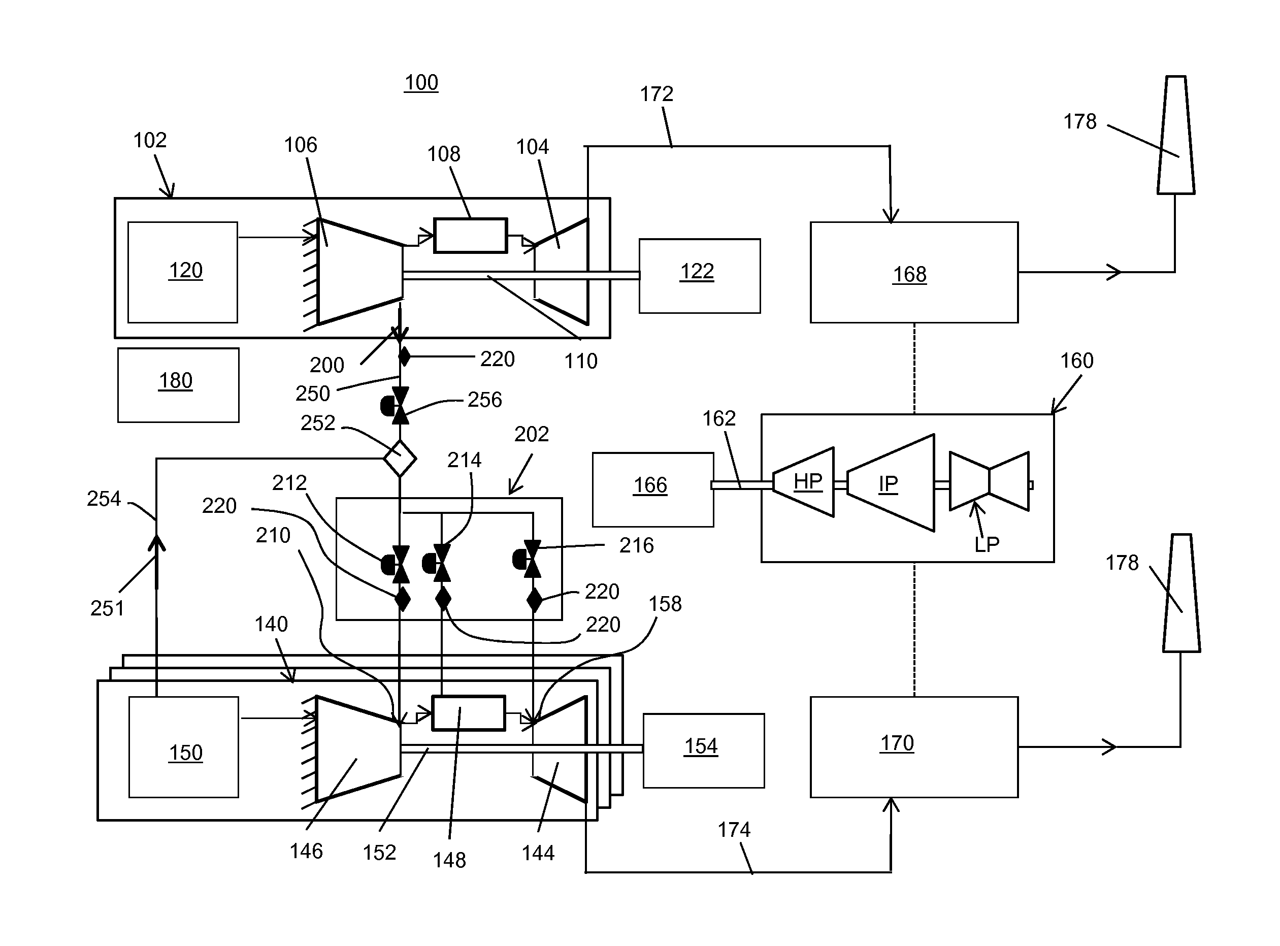
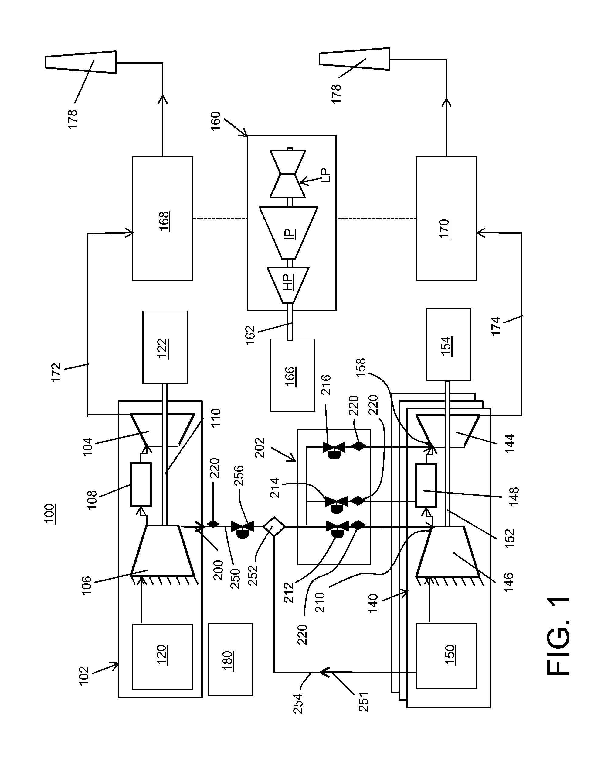
[0013]As indicated above, the disclosure provides a power generation system including a gas turbine system including a compressor that creates an excess air flow. Embodiments of the invention provide ways to employ the excess air flow to improve output of the power generation system.

[0014]Referring to FIG. 1, a schematic diagram of a power generation system 100 according to embodiments of the invention is provided. System 100 includes a first gas turbine system 102. First gas turbine system 102 may include, among other components, a first turbine component 104, a first integral compressor 106 and a first combustor 108. As used herein, first “integral” compressor 106 is so termed as compressor 106 and turbine component 104 may be integrally coupled together by, inter alia, a common compressor / turbine rotating shaft 110 (sometimes referred to as rotor 110). This structure is in contrast to many supplemental compressors that are separately powered, and not integral with turbine compone...


PUM


Abstract

A power generation system includes: a first gas turbine system including a first turbine component, a first integral compressor and a first combustor to which air from the first integral compressor and fuel are supplied, the first combustor arranged to supply hot combustion gases to the first turbine component, and the first integral compressor having a flow capacity greater than an intake capacity of the first combustor and/or the first turbine component, creating an excess air flow. A second gas turbine system may include similar components to the first except but without excess capacity in its compressor. A control valve system controls flow of the excess air flow to the second gas turbine system. An eductor may be positioned in the excess air flow path for using the excess air flow as a motive fluid to augment the excess air flow to the second gas turbine with additional air.

Description

CROSS-REFERENCE TO RELATED APPLICATIONS[0001]This application is related to co-pending U.S. application Ser. Nos. ______, GE docket numbers 280346-1, 280348-1, 280349-1, 280352-1, 280353-1, 280354-1, and 280355-1, all filed on ______.BACKGROUND OF THE INVENTION[0002]The disclosure relates generally to power generation systems, and more particularly, to a power generation system including a gas turbine system having a compressor creating an excess air flow and an eductor augmentation thereof.[0003]Power generation systems oftentimes employ one or more gas turbine systems, which may be coupled with one or more steam turbine systems, to generate power. A gas turbine system may include a multi-stage axial flow compressor having a rotating shaft. Air enters the inlet of the compressor and is compressed by the compressor blade stages and then is discharged to a combustor where fuel, such as natural gas, is burned to provide a high energy combustion gas flow to drive a turbine component. I...

Claims


Application Information

Patent Timeline
Patent Type & Authority Applications(United States)
IPC IPC(8): F01K23/10F02C6/00
CPCF02C6/00F01K23/10F01D25/12F02C3/04F02C3/13F02C3/30F02C6/18F02C9/18F02C3/32F02C6/08F05D2260/601Y02E20/16
Inventor EKANAYAKE, SANJIDAVIS, DALE JOELKLOSINSKI, JOSEPH PHILIPORENSTEIN, ROBERT MICHAELSCIPIO, ALSTON ILFORD
Owner GENERAL ELECTRIC CO
Why Eureka
Try Eureka