Header Mounting Frame

a header and mounting frame technology, applied in agricultural machines, agricultural tools and machines, adjusting devices, etc., can solve the problems of inability to cross-couple and adversely affect the fore-aft actuator, and achieve the effect of facilitating the pivoting of the intermediate frame and facilitating the pivoting of the header mounting fram

Active Publication Date: 2016-09-29
BLUE LEAF I P INC
View PDF12 Cites 15 Cited by
  • Summary
  • Abstract
  • Description
  • Claims
  • Application Information

AI Technical Summary

Benefits of technology

[0007]To this end, in accordance with an aspect of the present invention, there is provided an agricultural harvester. The agricultural harvester comprises a feeder, an intermediate frame pivotally mounted to the feeder to facilitate pivoting of the intermediate frame relative to the feeder with respect to a first axis of motion, and a header mounting frame pivotally mounted to the intermediate frame to facilitate pivoting of the header mounting frame relative to the intermediate frame with respect to a second axis of motion. Pivoting around the first axis of motion and the second axis of motion allows the header mounting frame to be moved with respect to the feeder in a fore-aft movement and a lateral tilt movement. At least one lateral tilt actuator is provided to actuate the header mounting frame in order to perform the lateral tilt movement. At least two fore-aft actuators are provided, each extending between a corresponding one of a first set of mounting positions at the feeder and a second set of mounting positions at the header mounting frame to actuate the header mounting frame in order to perform the fore-aft movement.
[0008]In the agricultural harvester, two fore-aft actuators are provided which both extend between the feeder and the header mounting frame. Thereby, the two fore-aft actuators pass the intermediate frame. This creates a direct connection between the feeder and the header mounting frame. This direct connection by two actuators significantly reinforces the header mounting frame support structure since the load of the header and impacts on the header will be divided between on the one hand the connection points between feeder and intermediate frame and between intermediate frame and header mounting frame, and on the other hand the two fore-aft actuators. Tests have shown that the connecting points and the header mounting frame can be formed significantly less strong compared to the prior art system while the risk of breaking of the connection points is less than prior art systems due to the two fore-aft actuators extending between the header mounting frame and the feeder. In this set-up, the load of the header is not only transmitted from header mounting frame to the feeder via the connecting points, but at least a portion of this load is directly transmitted from the header mounting frame via two fore-aft actuators to the feeder so that the connecting points are at least partially relieved. This results in a more rigid connection between header mounting frame and the feeder while allowing an automatic lateral tilt movement and an automatic fore-aft movement.
[0009]Desirably, the two fore-aft actuators are cross-coupled such that, in a predetermined fore-aft position of the two actuators, a retraction of one of the actuators results in an extension of the other of the two actuators and vice versa. A cross-coupling of the two fore-aft actuators significantly reduces the impact of a lateral tilt movement on the fore-aft position of the header. Because the two fore-aft actuators are arranged at a horizontal distance from one another, a lateral tilt movement will adversely affect the fore-aft actuators. The cross-coupling of the actuators allows one actuator to retract while the other actuator extends proportional to the retraction, so that the adverse affection of the two fore-aft cylinders is at least partially compensated.
[0010]Desirably, the two fore-aft actuators are dimensioned to each have an operating range that is at least 10% larger than the actuator acting range required to enable a maximum fore-aft movement when the lateral tilt actuator is in a predetermined neutral position. Thereby, further desirably, the two fore-aft actuator are arranged in such manner that the actuator acting ranges are substantially in the middle of the operating ranges of the actuators. The advantage of over-dimensioning the two fore-aft actuators is that in at least one of their extreme positions, for example the header tilted in its most forward (fore) or most rearward (aft) position, the two fore-aft cylinders still have some operating room to allow the cross-coupling between the actuators to work when a lateral tilt movement is applied to the header. Thereby, it will be clear that when an actuator is at its most extended or most retracted position, the cross-coupling will not work since further extension or further retraction of the actuator is not possible anymore. Therefore, over-dimensioning the operating range of the fore-aft actuators with respect to the acting range that is required to enable a maximum fore-aft movement in a neutral position of the lateral tilt actuator further improves the header mounting system.
[0012]Desirably, the fore-aft movement of the header mounting frame is defined as a movement of the header mounting frame with respect to the feeder about a first axis which is substantially horizontal and transverse to the forward driving direction of the agricultural vehicle. Further, desirably, the lateral tilt movement of the header mounting frame is defined as a movement of the header mounting frame with respect to the feeder about an axis which is substantially horizontal and parallel to the forward driving direction of the agricultural vehicle. Thereby, the lateral tilt movement allows the header to be tilted so that a left end of the header and a right end of the header show substantially the same distance to a ground surface. The lateral tilt movement allows to achieve such substantially the same distance even when the ground surface is not flat. The fore-aft movement allows to adjust the angle between the cutting knives, positioned at the leading edge of the header, and the ground surface so that this angle can be optimized depending on predetermined parameters.
[0014]Desirably, the lying support beam is located at an upper side of the header mounting frame and wherein the first set of mounting positions is located higher than the second set of mounting positions, such that the two fore-aft actuators carry at least a part of the weight of the header mounting frame. Alternatively, the lying support beam is located at the lower side of the header mounting frame, and wherein the first set of mounting positions is located lower than the second set of mounting positions such that the two fore-aft actuators carry at least a part of the weight of the header mounting frame. According to the first embodiment, the two fore-aft actuators extend upwards from a lying support beam which is positioned at an upper part of the header mounting frame, so that the upwardly extending fore-aft actuators carry at least a part of the weight of the header mounting frame, and at least a part of the weight of the header when the header is mounted to the header mounting frame. In an analogue manner, downwardly extending fore-aft actuators can carry a part of the weight of the header mounting frame so that less weight is to be carried by the connecting points.

Problems solved by technology

Because the two fore-aft actuators are arranged at a horizontal distance from one another, a lateral tilt movement will adversely affect the fore-aft actuators.
Thereby, it will be clear that when an actuator is at its most extended or most retracted position, the cross-coupling will not work since further extension or further retraction of the actuator is not possible anymore.

Method used


Image

  • Header Mounting Frame
  • Header Mounting Frame
  • Header Mounting Frame

Examples


Embodiment Construction

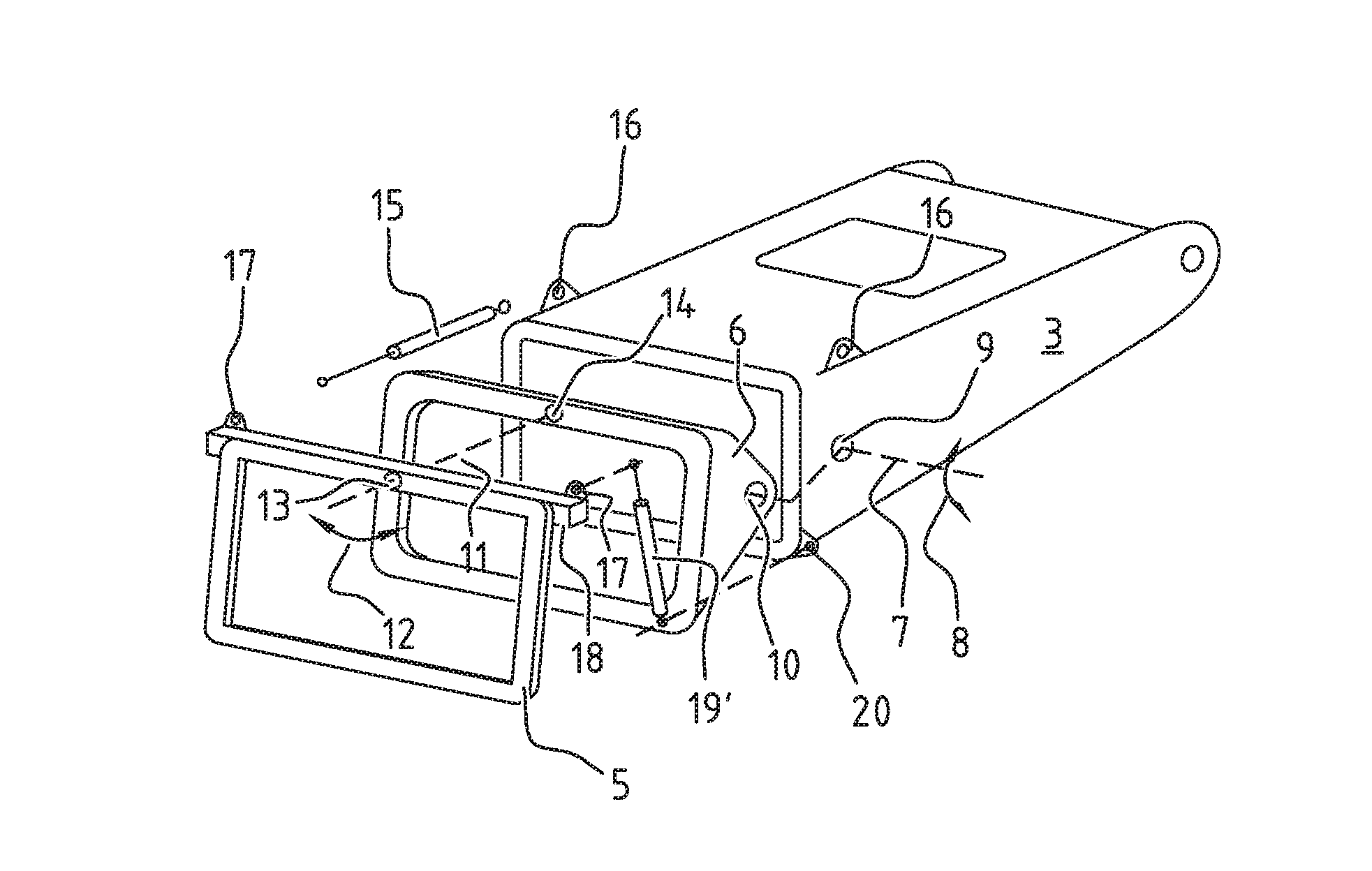
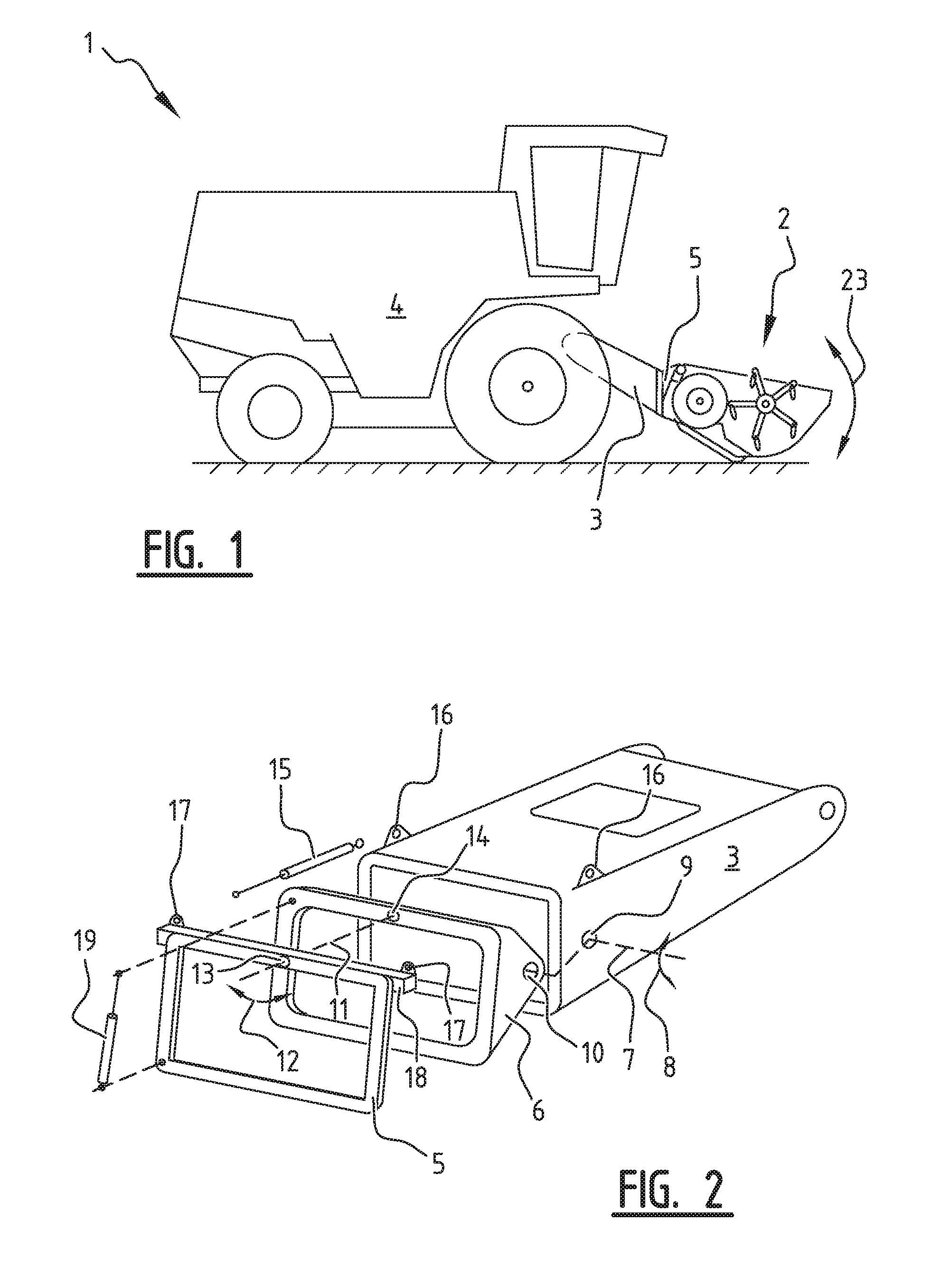
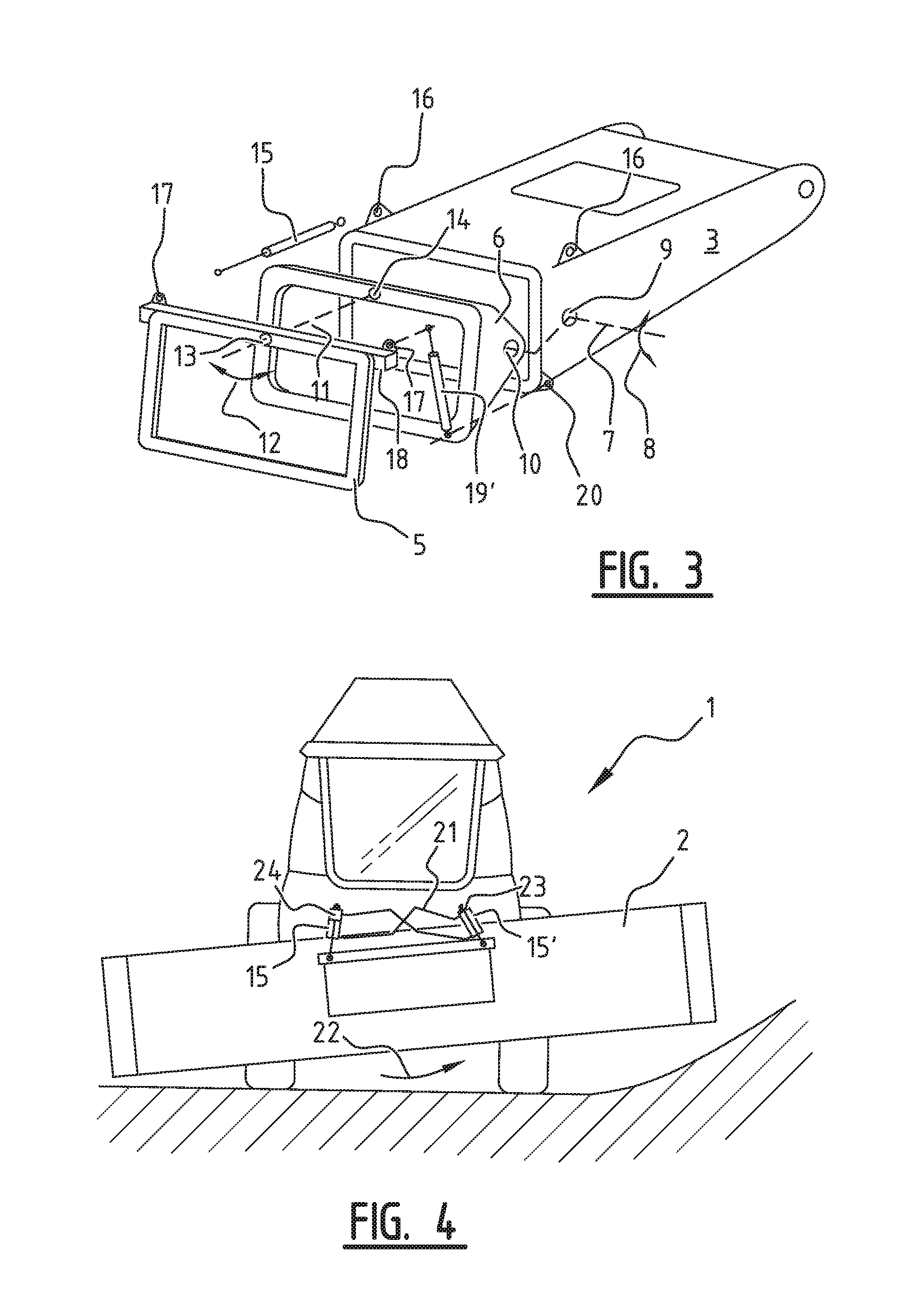
[0022]FIG. 1 shows a side view of an agricultural harvester (or vehicle) 1, in accordance with an exemplary embodiment of the present invention. In operation, a header 2 is connected to the agricultural harvester 1. The agricultural harvester 1 comprises a feeder 3 which is connected to the header 2 via a header mounting frame 5 provided at the frontal end of the feeder 3, and is provided for taking in harvested crop material from the header 2 towards the body 4 of the agricultural harvester 1. The header 2 has to be positioned in a fore-aft position with respect to the agricultural vehicle 1. Thereby the fore-aft position defines the angle between the cutting knives of the header and the ground surface. Tests have shown that an ideal fore-aft position depends on the type of crop material to be harvested. Therefore, the fore-aft position is desirably adaptable. This is implemented by allowing the header mounting frame 5 to perform a fore-aft movement, which is indicated in FIG. 1 wi...


PUM


Abstract

An agricultural harvester including a feeder. The feeder is pivotally mounted to an intermediate frame with respect to a first axis of motion. The intermediate frame is pivotally mounted to a header mounting frame with respect to a second axis of motion. Pivoting around the first axis of motion and the second axis of motion allows a fore-aft movement and a lateral tilt movement. At least one lateral tilt actuator is provided to actuate the header mounting frame in the lateral tilt movement. At least two fore-aft actuators are provided for extending between a first set of mounting positions at the feeder and a second set of mounting positions at the header mounting frame to actuate the header mounting frame in the fore-aft movement.

Description

CROSS REFERENCE TO RELATED APPLICATION[0001]This application claims priority to Belgium Application BE2015 / 5194 filed Mar. 27, 2015, which is incorporated herein by reference in its entirety.FIELD OF THE INVENTION[0002]The present invention relates to an agricultural harvester comprising a feeder and a header mounting frame, which is movably connected to the feeder.BACKGROUND OF THE INVENTION[0003]An agricultural harvester, in operation, carries a header for cutting crop material and transporting the crop material to the feeder of the agricultural harvester. The header is connected to the header mounting frame of the agricultural harvester. In recent years the dimensions of the header, and particularly the width of the header, has significantly increased so that also the weight of the header is significantly higher today. The width of the header requires the header mounting frame to be pivotally mounted to the feeder, directly or indirectly, to allow a lateral tilt movement of the h...

Claims


Application Information

Patent Timeline
Patent Type & Authority Applications(United States)
IPC IPC(8): A01B63/00A01D34/00
CPCA01D34/008A01B63/004A01D41/14A01D41/16A01D75/287
Inventor DE CONINCK, WILLEMDUQUESNE, FRANK R.G.
Owner BLUE LEAF I P INC
Why Eureka
Try Eureka